4-2 parts required for connection, 4-3 main/sub switching input setting, 4-4 wiring connections – KEYENCE SL-R11E User Manual
Page 36: English
Chapter 4 Wiring
4-10
4
English
ENGLISH
4-4 About the Light Interference Prevention Connection
4-4-1 What is the Light Interference Prevention Connection?
Be sure to read the “Safety Light Curtain SL-C Series Instruction Manual” if you plan to use this feature. By
establishing a light interference prevention connection, you can prevent light interference between 2 or more
sets of SL-C Series that are connected to the SL-R11E. This feature is active when the total number of
connected SL-R11E units is 4 or less.
To enable the light interference prevention function, the power to the main SL-R11E units and sub SL-R11E
units must be turned on. (If the power supply of a sub unit is turned OFF during operation, this unit and the
inferior sub units to it go to lockout condition and their operations are stopped.)
4-4-2 Parts Required for Connection
Name
Model
Manufacturer
Quantity
Notes
Connector
DF1E-3S-2.5C
HIROSE
2
KEYENCE also offers OP-42365 as an option
Crimp terminal DF1B-2022SC
ELECTRIC CO., LTD.
6
(set of 2 connectors and 6 crimp terminals).
Cable
2-wire shielded cable
Supplied by customer.
AWG #20 to 22
1 (30 m
(98.43 ft.)
or less)
4-4-3 Main/sub Switching Input Setting
One of the SL-R11E units sharing the light interference prevention connection should be set as the main,
while all remaining SL-R11E units are configured as subs. See “4-3-4 Connecting to Main/Sub Select Input
Terminal” (
➮ page 4-7) for information about how to make this setting.
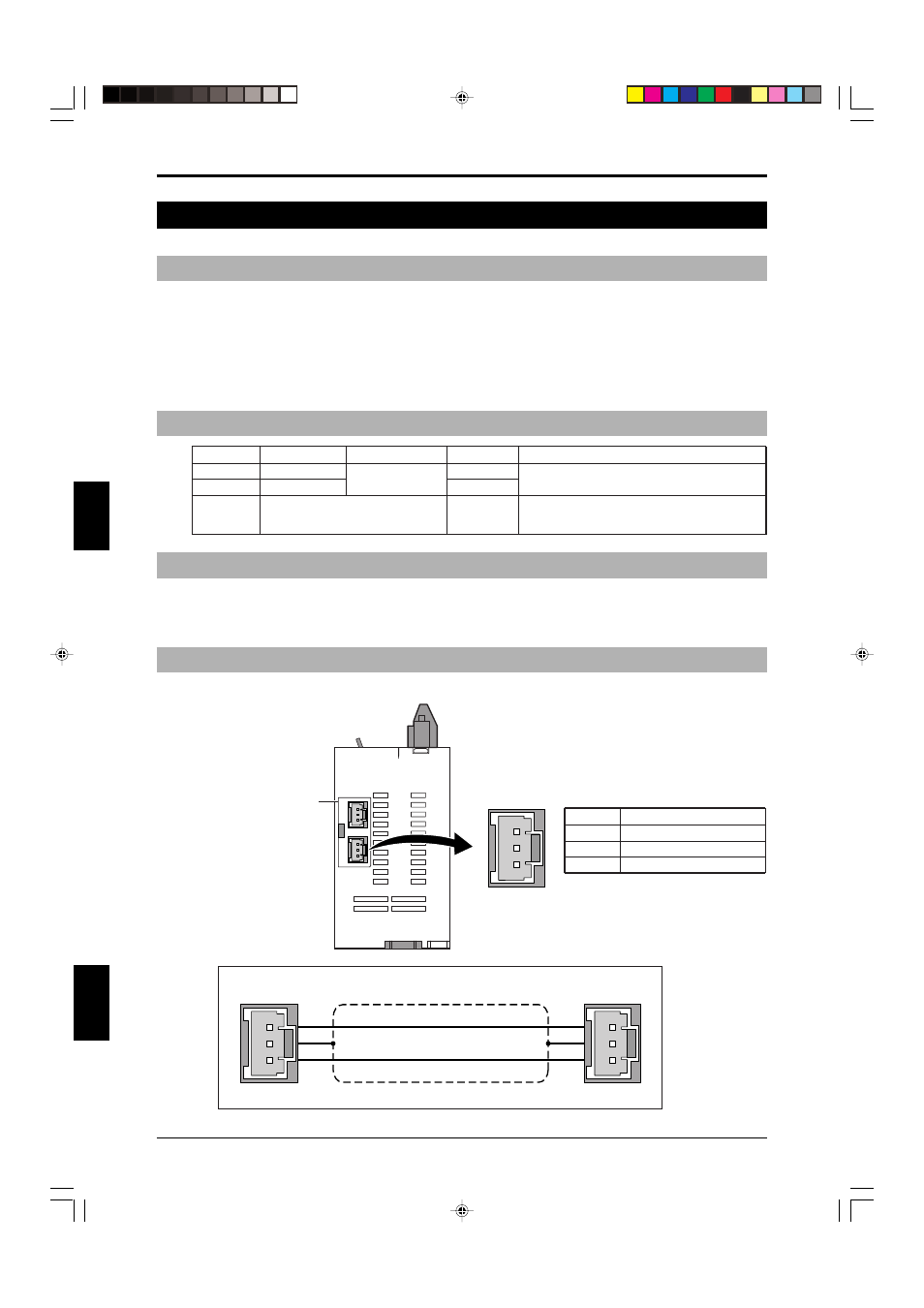
4-4-4 Wiring Connections
Remove the sticker on
the rear of the SL-R11E.
Pin No.
Description
1
Interference prevention (-)
2
Shielding (0 V)
3
Interference prevention (+)
3
2
1
Rear of SL-R11E
Wiring Diagram
3
2
1
3
2
1
Connector
2-wire shielded cable
Connector