4 mpce (machine primary control element) monitor, 5 main/sub setting, 6 test input – KEYENCE SL-R11E User Manual
Page 14: English
Chapter 2 Functions
2-2
2
English
ENGLISH
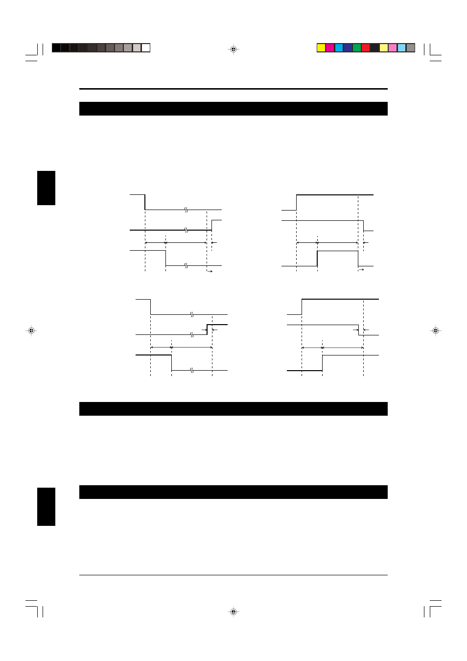
2-4 MPCE (Machine Primary Control Element) Monitor
MPCE (Machine Primary Control Element) is the machine's main control element and is used between the
SL-R11E control output (OSSD) and the machine to directly control the machine start/stop. The MPCE uses
safety relays, contactors, and so on, and inputting the feedback signal from these to the MPCE monitor input
terminal provided in the SL-R11E makes it possible to monitor MPCE errors. When an MPCE error causes
the OSSD and MPCE operation not to be linked, the SL-R11E immediately turns off the OSSD, and the SL-C
Series and SL-R11E go to the lockout condition.
➮ For details, See page 4-7 “4-3-3 Wiring to MPCE Monitor Input Terminal”.
ON
OFF
ON
OFF
Clear
Blocked
OSSD
20ms Max.
292ms Max.
ON
OFF
ON
OFF
Clear
Blocked
OSSD
MPCE monitor
input
20ms Max.
292ms Max.
Lockout
condition
Lockout
condition
MPCE monitor
input
*
*
ON
OFF
ON
OFF
Clear
Blocked
OSSD
MPCE monitor
input
20ms Max.
292ms Max.
ON
OFF
ON
OFF
Clear
Blocked
OSSD
MPCE monitor
input
20ms Max.
292ms Max.
*
*
* Depends on response time of machine’s MPCE
Timing chart when an error occurs
Timing chart when normal
2-5 Main/Sub Setting
This is set when making a light interference prevention connection to the SL-C Series. Be sure to read about
the light interference prevention connection from the “Safety Light Curtain SL-C Series Instruction Manual.”
The light interference prevention connection function is enabled only when a maximum of 4 SL-R11Es are
connected via a light interference prevention cable and the maximum number of beam axes of the SL-C
Series connected to the SL-R11E is 192, only one SL-R11E must be set to the main mode, and all of the
other SL-R11E that are connected via light interference prevention cables must be set to the sub mode.
➮ For details, See page 4-7 “4-3-4 Connecting to Main/Sub Select Input Terminal”.
2-6 TEST Input
The test input forcefully stops light beam transmission from the transmitter by using an external input.
The test input is used to see if the machine connected to the SL-C and SL-R11E can stop within the pre-
scribed time when the OSSD turns off.
For example, when the test input is performed with the SL-C in the normal state (when OSSD output is on
when all beam axes are clear of any obstruction), the OSSD is forced off and only one bar LED of the SL-C
flashes red. (However, this excludes when the Fixed Blanking function is used.)
This test input cannot be used when the SL-R12EX is used and the Programmable Muting Bank function is
enabled. Therefore, the Programmable Muting Bank function must be canceled to enable test input.