Carrier 50HCQ04---12 User Manual
Page 9
9
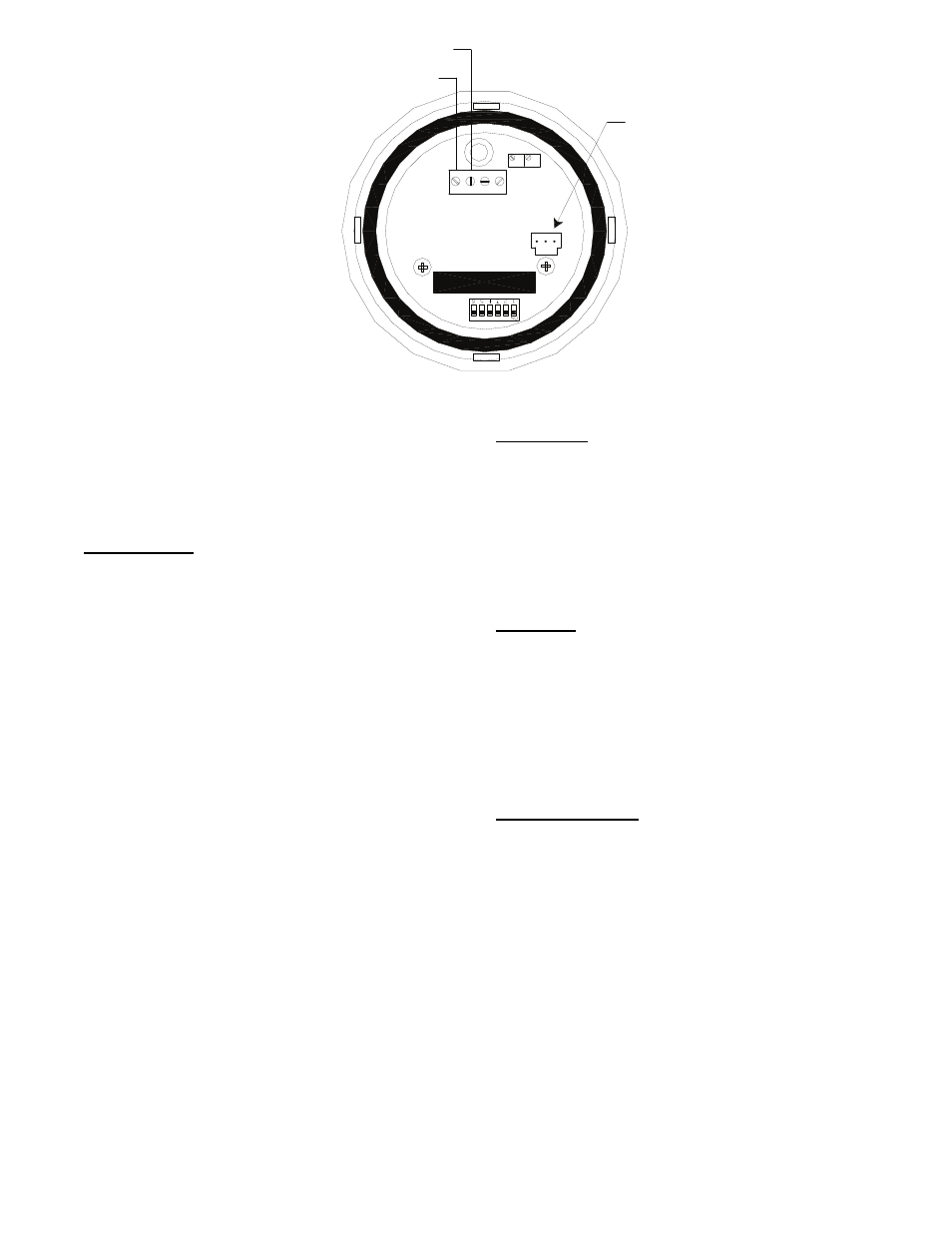
Relative Humidity Sensor
(Polarized Male Connector)
J4-1 or J4-4 + 24 VDC Supply Voltage
J4-2 or J4-5 (-) 4 to 20 mA Current Loop Output
to RTU-OPEN
4-20 VAC GND 0-5V
mA or or
VDC 0-10V
SPAN
ZERO
C10839
Fig. 9 -- Duct Relative Humidity Sensor Typical Wiring
To wire return air enthalpy sensor:
--MP
Connect the 4-20 mA In terminal on the enthalpy switch/
receiver to the 4-20 mA Out terminal on the return air
enthalpy sensor. Connect the 24-36 VDC Out terminal on
the enthalpy switch/receiver to the 24-36 VDC In terminal
on the return air enthalpy sensor. (See Fig 10.)
Fire Shutdown
The fire shutdown input is provided for unit shutdown in
response to a fire alarm or smoke detector. The fire
shutdown input is dedicated to input 5 and tells the
RTU-OPEN when to shutdown due to smoke detection or
fire alarm system.
The normal condition for fire
shutdown is there is no fire alarm. The unit may have
factory installed smoke detector(s); refer to the base unit
installation instructions for details on any adjustments
required during unit installation. Fire shutdown is always
factory configured for a normally open smoke detector.
For field installation of a smoke detector see instructions
for that specific accessory.
See below and the
troubleshooting section for wiring at the unit’s Low
Voltage Terminal Board (LVTB).
S
LVTB -- UNIT SHUTDOWN -- 24v OUT = 24 VAC
source
S
LVTB -- UNIT SHUTDOWN -- Smoke Alarm = Signal
input to RTU--OPEN
NOTE: Input 5 can also be wired into J5--3.
Filter Status
The filter status accessory is a field-installed accessory.
This accessory detects plugged filters. When installing
this accessory, the unit must have a free input (input 3, 5,
8, or 9). One of the dedicated functions (Humidistat, Fire
shutdown, Enthalpy, or Compressor safety) must not be in
use to configure Filter Status. Refer to the configuration
section for details on configuring inputs for specific
functions and state. Refer to Fig. 1 for wire terminations
at J5.
Fan Status
The fan status accessory is a field-installed accessory.
This accessory detects when the indoor fan is moving air.
When installing this accessory, the unit must have a free
input (input 3, 5, 8, or 9). One of the dedicated functions
(Humidistat, Fire shutdown, Enthalpy, or Compressor
safety) must not be in use to configure Fan Status. Refer
to the configuration section for details on configuring
inputs for specific functions and state. Refer to Fig. 1 for
wire terminations at J5.
Remote Occupancy
The remote occupancy accessory is a field-installed
accessory. This accessory provides an input to change the
units occupancy status. When installing this accessory, the
unit must have a free input (input 3, 5, 8, or 9). One of
the dedicated functions (Humidistat, Fire shutdown,
Enthalpy, or Compressor safety) must not be in use to
configure remote occupancy. Refer to the configuration
section for details on configuring inputs for specific
functions and state. Refer to Fig. 1 for wire terminations
at J5.