Sensor(s) (iaq and oaq) – Carrier 50HCQ04---12 User Manual
Page 6
6
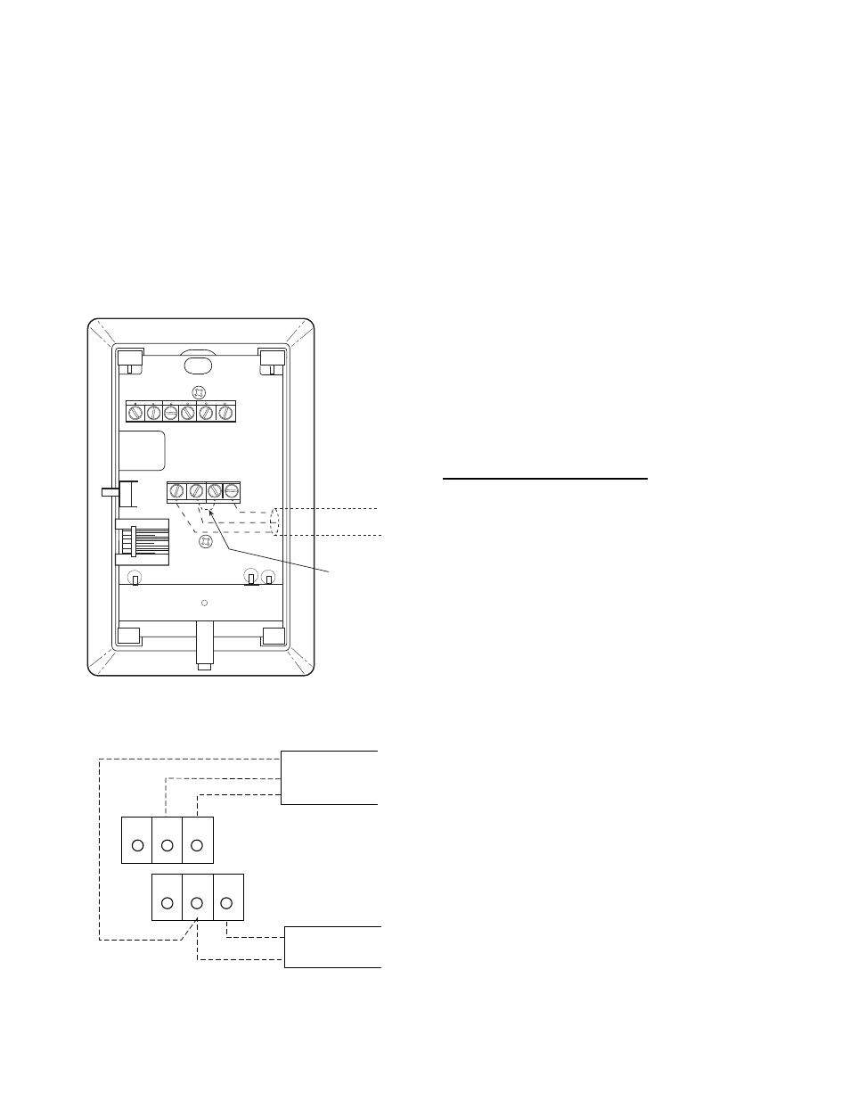
Resistive Non--Communicating Sensor Wiring
For sensor with setpoint adjustment up to 500 ft (152m),
use three-conductor shielded cable 20 gauge wire to
connect the sensor to the controller. For non set point
adjustment (slidebar) or return air duct sensor, an
unshielded, 18 or 20 gauge, two-conductor, twisted pair
cable may be used. Below is the list of the connections of
the SPT to the RTU-OPEN, refer to Fig. 3 and 4 for
typical connections at the sensor.
S
J20-1 = temperature sensor input (SEN)
S
J20-2 = sensor common
S
J20-3 = Setpoint adjustment input (SET)
NOTE:
See Fig. 5 for space temperature sensor
averaging. T55/56 Override button will no longer function
when sensors are averaged. Only Sensor 1 T56 STO input
can be used.
2
3
4
5
6
1
SW1
SEN
SET
Cool
Warm
BRN (GND)
BLU (SPT)
SENSOR WIRING
JUMPER
TERMINALS
AS SHOWN
BLK
(T56)
C07131
Fig. 3 -- Space Temperature Sensor
Typical Wiring (33ZCT56SPT)
OR
SET
SEN
OPB
COM- PWR+
BLU (SPT)
BLK (STO)
24 VAC
SENSOR
WIRING
POWER
WIRING
BRN (COM)
NOTE: Must use a separate isolated transformer.
Fig. 4 -- Space Temperature Sensor
Typical Wiring (33ZCT59SPT)
Rnet Communicating Sensor Wiring
The Rnet bus allows local communication with the
RTU-OPEN, including communicating sensors. The Rnet
bus can hold up to 6 devices in the following
combinations
wired
in
daisy-chain
or
hybrid
configuration:
S
1-4 SPS sensor(s)
S
1 SPPL, SPP, or SPPF sensor
S
1-4 SPS sensor(s), and 1 SPPL, SPP, or SPPF sensor
S
Any of the above combinations, plus up to 2
BACview
6
s
NOTE: Additional SPS sensors and BACview
6
must be
addressed. Use the jumpers on the SPS sensor’s circuit
board and refer to the BACview
6’
s installation instructions
for addressing.
For Rnet wiring up to 500ft (152m), use 18 AWG 4
conductor unshielded plenum rated cable.
The
RTU-OPEN’s J13-RNET connection has a 4 pin Phoenix
connector wired as described below, Fig. 6 shows sensor
Rnet wiring.
S
RNET -- 1 = Signal ground (GND)
S
RNET -- 2 = Signal (Rnet+)
S
RNET -- 3 = Signal (Rnet--)
S
RNET -- 4 = Power (+12v)
CO
2
Sensor(s) (IAQ and OAQ)
The indoor air quality (IAQ) and outdoor air quality
(OAQ) sensors monitor carbon dioxide (CO
2
) levels. This
information is used to monitor the quality of air in terms
of parts per million (PPM). The same sensor is used for
inside, outside, and duct monitoring, except an aspirator
box is required for outside and duct mounting. The CO
2
sensor is preset for a range of 0 to 2000 ppm and a linear
mA output of 4 to 20. The rooftop unit may have a factory
installed CO
2
sensor on the side of the economizer
assembly in the return air section of the unit and is
pre-wired and pre-configured at the factory. For field
installed sensors, a field supplied transformer must be
used to power the sensor.
Refer to the instructions
supplied with the CO
2
sensor for electrical requirements
and terminal locations. RTU-OPEN configurations must
be changed after adding a CO
2
sensor. See below and Fig.
7 for typical CO
2
sensor wiring.
S
J4--2 or J4--5 = 4--20mA signal input
S
J4--3 or J4--6 = signal common
NOTE: The factory used J4-2&3 for CO
2
(IAQ) sensor
inputs.
Combination Temperature and CO
2
Sensor
If using a combination temperature and CO
2
sensor
(33ZCT55CO2 or 33ZCT56CO2), refer to the installation
instructions provided with the sensor.