Command parameter list for gt2 series, 3 explicit messaging – KEYENCE DL-DN1 User Manual
Page 58
3-3 Explicit Messaging
3-28
- DeviceNet Compatible Network Unit DL-DN1 User’s Manual (GT2) -
3
Co
mm
u
ni
c
a
ting
w
ith t
he G
T
2
s
er
ie
s
*1
*2
"Error information list" (page 3-8)
*3
This is not available with the GT2-100 series. Only the default value of effective
ID is read, regardless of the effective ID setting.
*4
The function of DL-DN1 only, which responds to explicit messaging synchro-
nously with I/O communication. This function does not guarantee synchronism
of the whole system, including PLC or master equipment.
Command Parameter List for GT2 Series
The following tables provide command parameters for the GT2 series. The two types
of parameters are: motion command parameters and setting/status command
parameters.
Motion command parameters
For the communication methods using motion command parameters, see
a Motion Command to a Sensor Amplifier" (page 3-23).
N: ID number of sensor amplifier. For example, if the ID number is 13, then N = 13
(DEC).
InstID: Instance ID; AttrID: Attribute ID
0
8E
Comparator
value "under"
If the comparator values for sensor amplifi-
ers (ID 01 to ID 15) are "under" (-FFFF),
they are output by assigning them to bits 0
- 14.
R
WORD
0
0: Normal value
1: Under
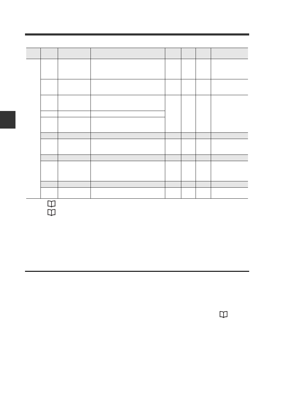
8F
Comparator
value "over"
If the comparator values for sensor amplifi-
ers (ID 01 to ID 15) are "over" (FFFF), they
are output by assigning them to bits 0 - 14.
R
WORD
0
0: Normal value
1: Over
90
Comparator
value ID 01
Reads the comparator value of ID 01.
Same as the comparator value used in I/O
communication.
R
DINT
0
-2147483648 to
2147483647
~
9E
Comparator
value ID 15
Reads the comparator value of ID 15.
Same as the judgement value used in I/O
communication.
9F to B0 System reserved
B1
Number of
sensor amplifier
units connected
Reads the number of connected sensor
amplifiers.*3
R
UINT
0
1 to 15
B2 to B3 System reserved
B4
Explicit message
response method
If synchronous response is used, response
occurs synchronously with I/O communica-
tion.*4
R/W
UINT
0
0: Immediate
response
1: Synchronous
response
B5 to B9 System reserved
BA
Operating mode
switch status
Set status of operating mode setting
switch: switch 1 (LSB) to switch 4 (MSB)
R
UINT
0
0 to 15
0: OFF, 1: ON
InstID
(DEC)
AttrID
(HEX)
Name
Description
Attribute
Data
type
Default
value
Parameter range