Device maps, Device maps -7, Output + current value" mode – KEYENCE DL-DN1 User Manual
Page 37: Status, 2 i/o communication, Co mm u ni c a ting w ith t he g t 2 s er ie s
3-2 I/O Communication
3-7
3
Co
mm
u
ni
c
a
ting
w
ith t
he G
T
2
s
er
ie
s
- DeviceNet Compatible Network Unit DL-DN1 User’s Manual (GT2) -
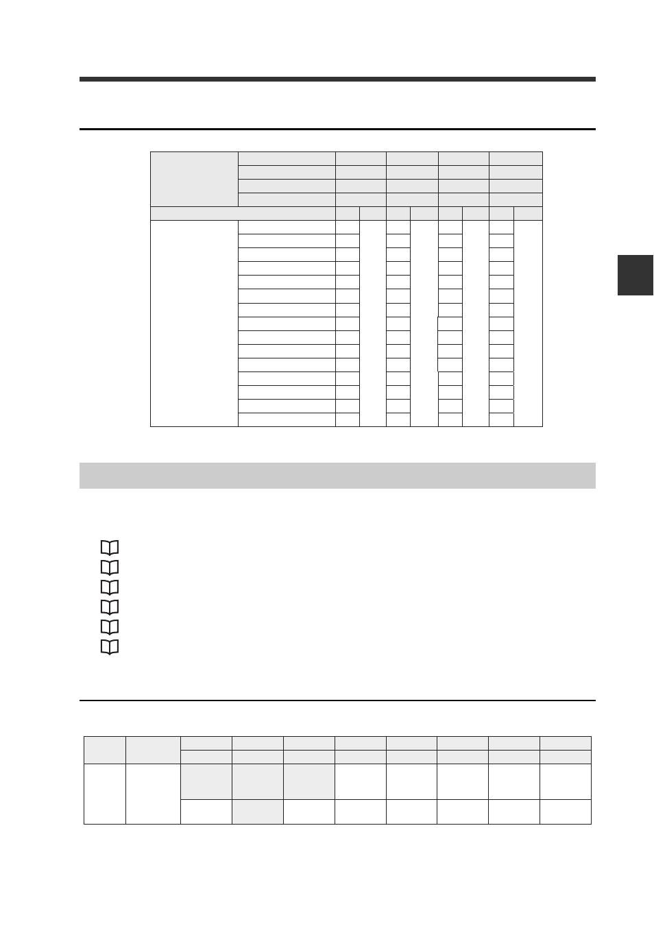
"5-output + current value" mode
The device map varies depending on the operating mode of the DL-DN1.
Access each device in a manner suitable for the selected operating mode.
"Comparator Value (P.V. Value)" (page 3-10)
"Rewrite setting value" (page 3-14)
Status
IN area
n: The first device number assigned to the DL-DN1
5-output + current
value
No extended mode
Yes
-
-
-
5-input
-
Yes
Yes
Yes
Bank change
-
-
Yes
-
Setting value rewrite
-
-
-
Yes
Area
IN
OUT
IN
OUT
IN
OUT
IN
OUT
Number of sensor
amplifi ers
1
18
0
28
10
32
14
40
40
2
22
32
36
44
3
26
36
40
48
4
30
40
44
52
5
34
44
48
56
6
38
48
52
60
7
42
52
56
64
8
46
56
60
68
9
50
60
64
72
10
54
64
68
76
11
58
68
72
80
12
62
72
76
84
13
66
76
80
88
14
70
80
84
92
15
74
84
88
96
(bytes)
Device Maps
Device
(DEC)
Name
Bit 7
Bit 6
Bit 5
Bit 4
Bit 3
Bit 2
Bit 1
Bit 0
Bit 15
Bit 14
Bit 13
Bit 12
Bit 11
Bit 10
Bit 9
Bit 8
n
Status
Reserved
Reserved
Reserved
Error ID
number
(MSB)
Error ID
number
Error ID
number
Error ID
number
Error ID
number
(LSB)
Error state Reserved
Sensor
ready
Error code
(MSB)
Error code Error code Error code
Error code
(LSB)