Output, 2 i/o communication, Co mm u ni c a ting w ith t he g t 2 s er ie s – KEYENCE DL-DN1 User Manual
Page 39
3-2 I/O Communication
3-9
3
Co
mm
u
ni
c
a
ting
w
ith t
he G
T
2
s
er
ie
s
- DeviceNet Compatible Network Unit DL-DN1 User’s Manual (GT2) -
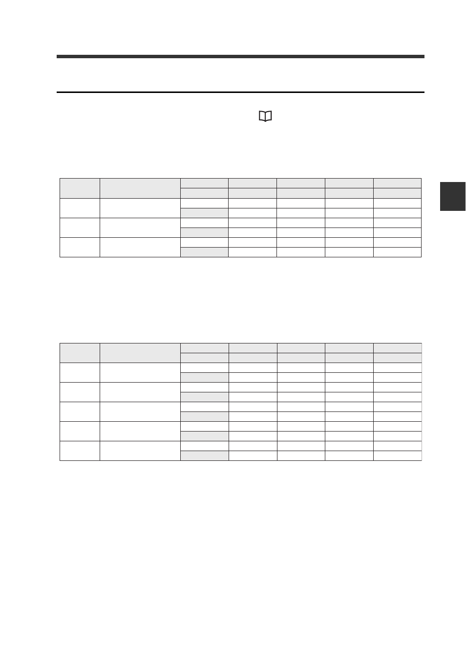
Output
Sensor amplifier ID numbers 01 to 15 are assigned to bits 0 to 14, respectively.
For details of communication methods, see
"Reading an output from a sensor
3-output mode
IN area
n: The first device number assigned to the DL-DN1
The device assignments are the same for all 3-output modes including extended
modes.
All 5-output modes
IN area
n: The first device number assigned to the DL-DN1
The device assignments are the same for all 5-output modes including extended
modes.
Device
(DEC)
Name
Bit 7
Bit 6
···
Bit 1
Bit 0
Bit 15
Bit 14
···
Bit 9
Bit 8
n+1
HIGH
ID08
ID07
···
ID02
ID01
Reserved
ID15
···
ID10
ID09
n+2
LOW
ID08
ID07
···
ID02
ID01
Reserved
ID15
···
ID10
ID09
n+3
GO
ID08
ID07
···
ID02
ID01
Reserved
ID15
···
ID10
ID09
Device
(DEC)
Name
Bit 7
Bit 6
···
Bit 1
Bit 0
Bit 15
Bit 14
···
Bit 9
Bit 8
n+1
HIGH
ID08
ID07
···
ID02
ID01
Reserved
ID15
···
ID10
ID09
n+2
LOW
ID08
ID07
···
ID02
ID01
Reserved
ID15
···
ID10
ID09
n+3
GO
ID08
ID07
···
ID02
ID01
Reserved
ID15
···
ID10
ID09
n+4
HH
ID08
ID07
···
ID02
ID01
Reserved
ID15
···
ID10
ID09
n+5
LL
ID08
ID07
···
ID02
ID01
Reserved
ID15
···
ID10
ID09