Command parameter list, Command parameter list -27, Common command parameter list – KEYENCE DL-DN1 User Manual
Page 57: 3 explicit messaging, Co mm u ni c a ting w ith t he g t 2 s er ie s
3-3 Explicit Messaging
3-27
3
Co
mm
u
ni
c
a
ting
w
ith t
he G
T
2
s
er
ie
s
- DeviceNet Compatible Network Unit DL-DN1 User’s Manual (GT2) -
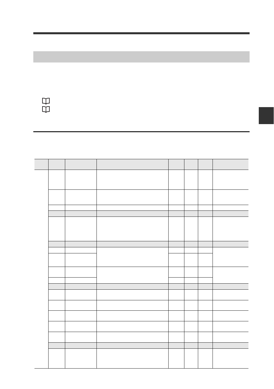
The following tables list the command parameters used in explicit messaging to read/
write the settings and status of sensor amplifiers and to issue motion commands.
For details about how the master unit performs explicit messaging using command
parameters, see:
"Issuing a Motion Command to a Sensor Amplifier" (page 3-23)
"Reading/Writing Settings or Status of a Sensor Amplifier" (page 3-24)
Common Command Parameter List
The table below describes command parameters which are common to the DL-DN1.
InstID: Instance ID; AttrID: Attribute ID
Attribute R: Read; R/W: Read/Write
Command Parameter List
InstID
(DEC)
AttrID
(HEX)
Name
Description
Attribute
Data
type
Default
value
Parameter range
0
64
Status
Bit 0 - 12: Unused
Bit 13: Sensor ready
Bit 14: Warning state
Bit 15: Error state
R
WORD
0
*1
65
Error state
The error state values of sensor amplifiers
(ID 01 to ID 15) are output as they are
assigned to bits 0 - 14.
R
WORD
0
0: No Error
1: Error
66
Warning state
Not used with the GT2 series.
R
WORD
0
−
67
System reserved
68
Current value
property
This property is output by assigning sensor
amplifiers (ID 01 to ID 15) bits 0 - 14.
The output occurs when the measured
value is non-numeric: "over," "under," or
"invalid."
R
WORD
0
0: Normally mea-
sured value
1: "over," "under," or
"invalid"
69 to 6B System reserved
6C
Error ID number Error details.
If there are errors with multiple ID numbers,
the error information for the smallest ID
number is output.
R
UINT
0
*2
6D
Error code
R
UINT
0
6E
Warning ID
number
Not used with the GT2 series.
R
UINT
0
−
6F
Warning code
R
UINT
0
70 to 73 System reserved
74
HIGH
The HIGH state is output by assigning sen-
sor amplifiers (ID 01 to ID 15) bits 0 - 14.
R
WORD
0
0: OFF
1: ON
75
LOW
The Low state is output by assigning sen-
sor amplifiers (ID 01 to ID 15) bits 0 - 14.
R
WORD
0
0: OFF
1: ON
76
GO
The GO state is output by assigning sensor
amplifiers (ID 01 to ID 15) bits 0 - 14.
R
WORD
0
0: OFF
1: ON
77
HH
The HH state is output by assigning sensor
amplifiers (ID 01 to ID 15) bits 0 - 14.
R
WORD
0
0: OFF
1: ON
78
LL
The LL state is output by assigning sensor
amplifiers (ID 01 to ID 15) bits 0 - 14.
R
WORD
0
0: OFF
1: ON
79 to 8C System reserved
8D
Comparator
value "invalid"
If the comparator values for sensor amplifi-
ers (ID 01 to ID 15) are invalid
(-----), they are output by assigning them to
bits 0 - 14.
R
WORD
0
0: Normal value
1: Invalid