Checkline TI-MVX User Manual
Page 8
2.3 Measure
The TI-MVX is now ready to measure. There are four different measurement
view options, each with a specific purpose. The steps below outline how to tog-
gle between the different view mode options:
Selecting the Measurement View Option
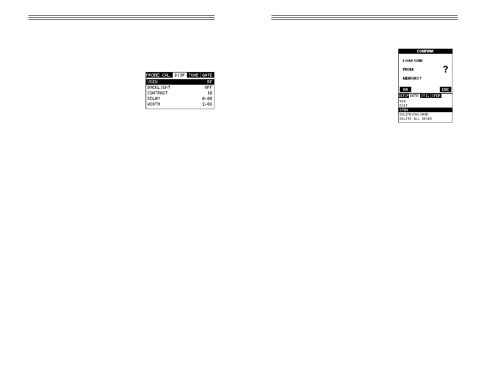
1) Press the MENU key once to activate the
menu items tab. Press the MENU key multiple
times to tab right and the ESC key multiple
times to tab left until the DISP menu is high-
lighted and displaying the submenu items.
2) Use the UP and DOWN arrow keys to scroll
through the sub menu items until VIEW is highlighted.
3) Use the LEFT and RIGHT arrow keys to scroll the view options.
4) Once the view is displayed, press the MEAS key to return to measurement
mode.
RF: Is useful to see exactly what the signal looks like directly around the detect
point. Use this view only when viewing smaller ranges (zoomed in) around the
detection point. This can be done manually by adjusting the delay and width set-
tings.
RECTIFIED (RECT): Displays the entire range being scanned. This screen is
useful to “get the big picture” when viewing wide ranges (zoomed out). The point
which is triggering the digital thickness reading (called the detect) is displayed as
a vertical dashed line.
BSCAN: The Time Based B-Scan provides the user with a cross sectional view
of the material being tested. This mode is useful when there is concern regard-
ing the profile of the blind surface. This can also be a useful view when scanning
for pits and flaws.
-8-
2) Use the UP and DOWN arrow keys to scroll through the sub menu items until
OPEN is highlighted.
3) Press the ENTER key to display the Grid List
Box.
4) Use the UP and DOWN arrow keys to scroll
through the grids until the target grid is highlight-
ed.
5) Press the ENTER key to activate the
confirmation screen.
6) Press the OK key to load the grid from memory.
7) Press the MEAS key to return to the measure
screen.
-73-