Checkline TI-MVX User Manual
Page 29
CHAPTER SIX: MAKING MEASUREMENTS
The steps involved in making measurements are detailed in this section. The
following sections outline how to setup and prepare your TI-MVX for field use.
In pulse-echo modes, the probe zero must be measured on the reference disk
(battery disk) attached to the top of the instrument. This compensates for varia-
tion in the transducer. In all modes the sound velocity must be determined. The
sound velocity is used to convert the transit time to a physical length. The sound
velocity can be selected from a material chart in the manual, selected from a
material list in the TI-MVX, or for greater precision, determined from a sample of
the test material that has been mechanically measured. To enter the velocity
from a table, look up the material on the chart in the appendix of this manual
and refer to the section below on Calibration to a Known Velocity. To determine
the velocity of a single sample, refer to the Material Calibration section on page
32.
When measuring curved materials, it is more accurate to calibrate from two test
points, one at the minimum limit of the target thickness and one at the maximum
limit. In this case the reference disk mounted to the TI-MVX is not used. This is
called two-point calibration and is described on page 34.
6.1
Selecting The Transducer Type
The first step in using the TI-MVX is to select the transducer type from the
transducer list located in the tabbed menu items by frequency and diameter.
By selecting the transducer type from a predefined list, the TI-MVX can recall
specific properties about the transducer. Note: Once the transducer has been
selected, the TI-MVX will store and recall this transducer type every time the
TI-MVX is powered on/off. The type will only change if the user physically selects
another type from the list, or selects a previously saved setup. Therefore, if you
have previously gone through this section and selected the transducer you are
using, proceed to the next section. Use the following steps to select your trans-
ducer type.
Note: Be sure the transducer type selected is the same as the transducer
plugged into the TI-MVX. Failure to do this will result in erroneous measure-
ments
-29-
brings all the fine adjustments into consideration, and demonstrates the versatili-
ty of having fully functional scope rather than a basic digital thickness gauge.
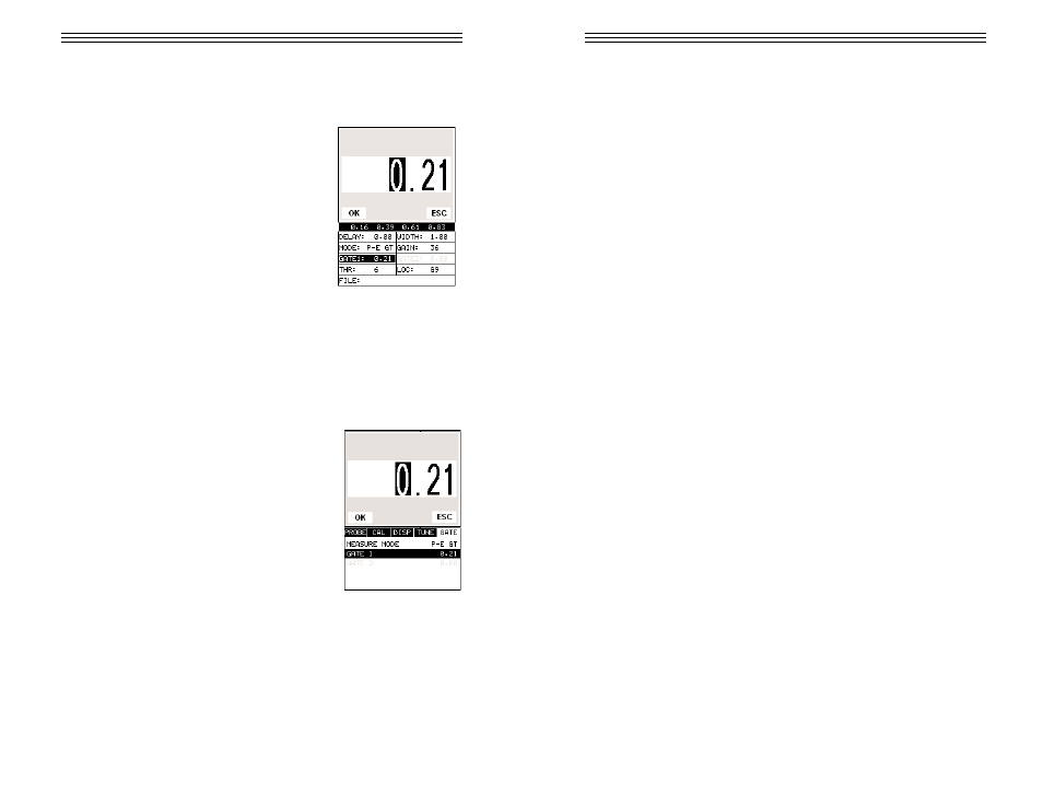
Adjusting Gate1 using the Hot Menus
1) Press the MEAS key once to activate measure
menu items. Press the MEAS key multiple times
to move right and the ESC key multiple times to
move left until the GATE 1 cell is highlighted.
2) Press the UP, DOWN, LEFT, and RIGHT arrow
keys to scroll the highlighted value.
3) Alternatively, press the ENTER key to display
the Digits Edit Box.
4) Press the UP and DOWN arrow keys to scroll
the highlighted value.
5) Press the LEFT and RIGHT arrow keys to
scroll the digit locations.
6) Repeat steps 4 & 5 until the GATE 1 value is correctly displayed.
7) Press the OK key to return to the measurement screen, or ESC to cancel
entering the GATE 1 value.
The user can also access and adjust the gate from the tabbed menus. However,
this method is more tedious than making the adjustments using the Hot Menus.
The procedure using the tabbed menus is outlined below:
Adjusting Gate1 using the Tabbed menus
1) Press the MENU key once to activate the menu
items tab. Press the MENU key multiple times to
tab right and the ESC key multiple times to tab
left until the GATE menu is highlighted and dis-
playing the submenu items.
2) Use the UP and DOWN arrow keys to scroll
through the sub menu items until GATE is high-
lighted.
3) Press the LEFT and RIGHT arrow keys to
scroll the value. When the correct gate is being
displayed, proceed to step 8.
4) Alternatively, press the ENTER key to display
the Digits Edit Box.
-52-