Checkline TI-MVX User Manual
Page 20
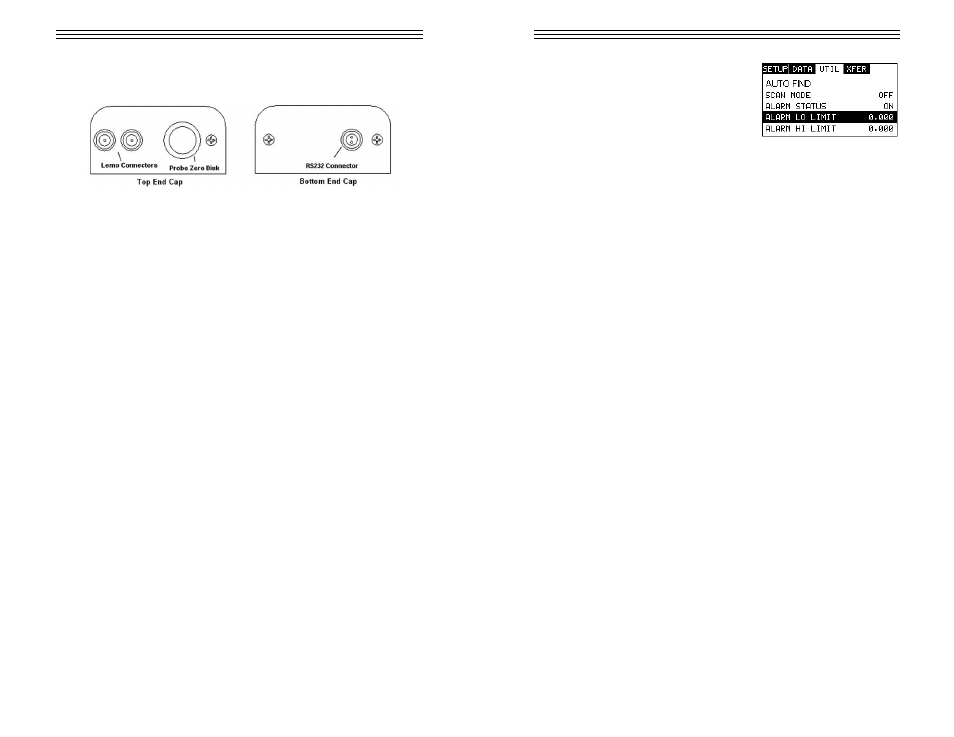
3.19 Top & Bottom End Caps
The top & bottom end panels are where all connections are made to the
TI-MVX. The diagram above shows the layout and description of the connectors:
Transducer Connectors
Refer to Diagram: The transducer connectors, and battery cover/probe zero disk
are located on the TI-MVX’s top end cap. The transducer connectors are of type
Lemo “00”. Note: There is no polarity associated with connecting the transducer
to the TI-MVX.
Probe Zero Disk & Battery Cover
Refer to Diagram: The Battery cover is the large round disk shown in the dia-
gram. Note: This same disk is also used as a probe zero disk. Simply remove the
cover when replacing the batteries (3 AA cells). When performing a probe zero
function, simply place the transducer on disk making firm contact. Important: Be
sure to follow the polarity labels located on the back label of the TI-MVX. Note:
Rechargeable batteries can be used, however they must be recharged outside of
the unit in a stand alone battery charger.
RS-232 Connector
Refer to Diagram: The RS-232 connector, located on the bottom end cap, is a
2 pin female Lemo connector. It is designed to connect directly from the TI-MVX
to a standard AT serial port on a PC. The cable supplied with the TI-MVX is a
Lemo to 9 pin serial cable.
Note: This connector is also used to upgrade the TI-MVX with the latest version
of firmware.
-20-
Setting the Alarm LO Limit
1) Assuming the ALARM STATUS is ON,
use the UP and DOWN arrow keys to scroll
through the sub menu items until ALARM
LO LIMIT is highlighted.
2) Press the LEFT and RIGHT arrow keys to scroll the value. When the correct
alarm value is being displayed, proceed to step 7.
3) Alternatively, press the ENTER key to display the Digits Edit Box.
4) Press the UP and DOWN arrow keys to scroll the highlighted value.
5) Press the LEFT and RIGHT arrow keys to scroll the digit locations.
6) Repeat steps 4 & 5 until the ALARM LO value is correctly displayed.
7) If only one limit will be used, press the MEAS key to return to the measure-
ment screen and begin taking readings. Otherwise, continue on to set the
ALARM HI LIMIT.
Setting the Alarm HI Limit
1) Assuming the ALARM STATUS is ON,use the UP and DOWN arrow keys to
scroll through the sub menu items until ALARM HI LIMIT is highlighted.
2) Press the LEFT and RIGHT arrow keys to scroll the value. When the correct
alarm value is being displayed, proceed to step 8.
3) Alternatively, press the ENTER key to display the Digits Edit Box.
4) Press the UP and DOWN arrow keys to scroll the highlighted value.
5) Press the LEFT and RIGHT arrow keys to scroll the digit locations.
6) Repeat steps 4 & 5 until the ALARM HI value is correctly displayed.
7) Press the OK key to set the ALARM HI value and return to the menu screen,
or ESC to cancel entering the ALARM HI value.
8) Press the MEAS key to return to the measurement screen and begin taking
readings.
9.5 Polarity
The TI-MVX is equipped with an option to select the polarity, or phase +/-, for the
purpose of detection. The phase can be a valuable feature to have when the sig-
nal returning from the test material is marginal, a low frequency transducer is
being used, and the user has a very weak positive or negative cycle, while trying
to measure very thick materials. There is a possibility that signal will become so
weak that it falls below the threshold, and peak jumps to the next
-61-