Checkline TI-MVX User Manual
Page 30
Selecting the Transducer Type
1) Press the MENU key once to activate the menu
items tab. Press the MENU key multiple times to
tab right and the ESC key multiple times to tab
left until the PROBE menu is highlighted and
displaying the submenu items.
2) Use the UP and DOWN arrow keys to scroll
through the sub menu items until TYPE is
highlighted.
3) Press the ENTER key to display the list of
transducer types.
4) Press the UP and DOWN arrow keys to scroll
through the transducer list until the appropriate type is highlighted.
5) Press the ENTER key to display the confirmation screen.
6) Press the OK key to select the transducer and return to the menu screen, or
ESC to cancel the material selection.
Now that the proper transducer has been selected and connected to the TI-MVX,
the measurement mode must be chosen according to the type of application.
Following the recommendations in the prior chapter, there are three different
ways to select the measurement mode as follows:
Selected from a Setup
Important Note: Stored setups will save all the
parameters of the TI-MVX. Therefore, if a transduc-
er was selected in the previous section and a
setup is now being recalled, the transducer saved
in the setup will overwrite the transducer previously
selected. Be sure the transducer saved with the
setup is the same as the transducer currently
being used. Alternatively, you can select a trans-
ducer again after recalling a setup. This will over-
ride the transducer saved with the setup.
1) Press the MENU key once to activate the menu
items tab. Press the MENU key multiple times to
tab right and the ESC key multiple times to tab left
until the SETUP menu is highlighted and displaying the submenu items.
2) Use the UP and DOWN arrow keys to scroll through the sub menu items until
OPEN is highlighted.
-30-
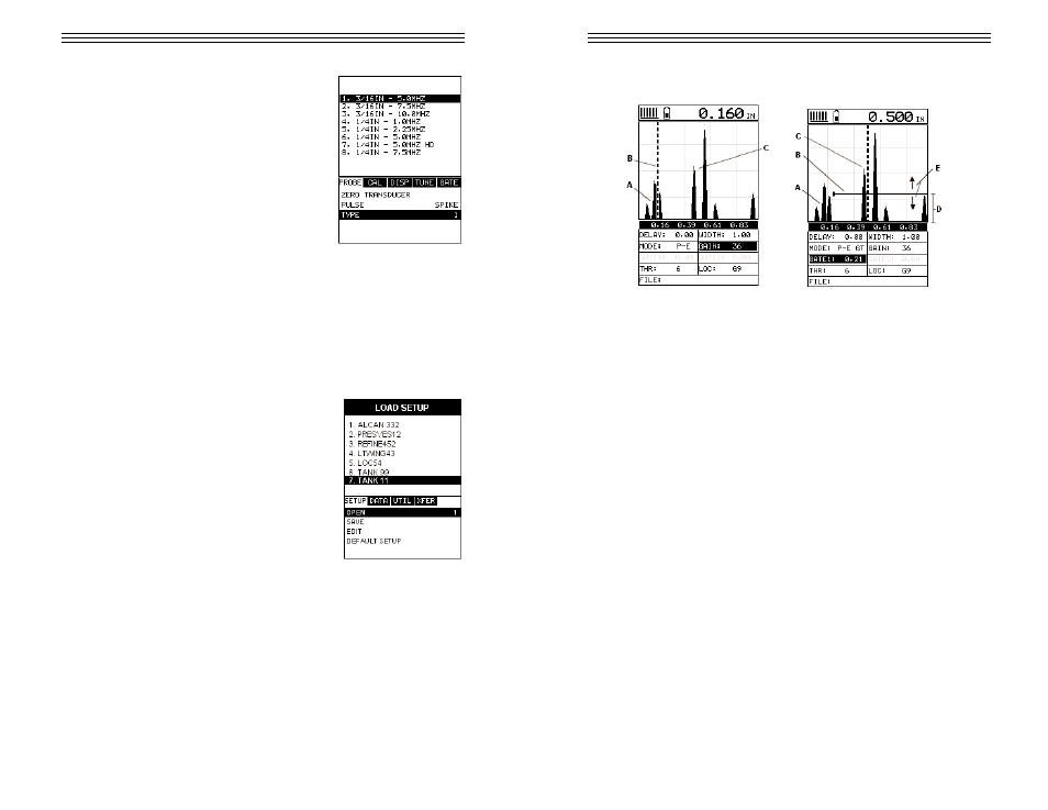
SURFACE NOISE PROBLEM
NO GATE
W/GATE
The diagrams above illustrate a typical surface noise condition. Refer to the NO
GATE diagram: (A) refers to the noise in front of the actual back wall signal (C).
Notice that without a gate activated, the TI-MVX is detecting on the noise (A) as
shown at point (B). However, the true measurement should be taken at point (C).
Given the threshold and gain levels the TI-MVX is currently set to in the NO
GATE diagram, the amplitude from the noise is sufficient enough to cause the
TI-MVX to detect, or measure the noise rather than the true back wall thickness
(C). Therefore, the TI-MVX is making an incorrect reading at point (B).
Now refer to the W/GATE diagram. The horizontal line at the top of (D), is
GATE1. The start point of GATE1 has been adjusted to just beyond the noise (A)
so that the TI-MVX ignores the noise and detects the true back wall (C). Note:
the TI-MVX will only detect on signals that are located inside the dimensions of
GATE1 (B). Therefore, the TI-MVX cannot see (A) at all, with respect to the start-
ing point of (B). Also notice, the THR (threshold) level is the height of the dis-
tance (D) from the baseline. Zero threshold is indicated by the bottom of the
range (D), and THR: 6 (threshold) is indicated at the top of the range at (D).
Therefore, the vertical height of GATE1 is the THR (threshold) level. The thresh-
old level can be increased to decrease sensitivity, or decreased to increase sen-
sitivity.
If the threshold level was increased in the NO GATE diagram, so that the level
was higher than the amplitude of the noise (A), the TI-MVX would have detected
on the true back wall (C). Alternatively, if the gain level was decreased, the sig-
nal amplitude of the noise (A) would have decreased below the threshold level,
and the TI-MVX would have also detected the true back wall (C). This example
-51-