Checkline TI-MVX User Manual
Page 13
3.2
Probe – Menu
Zero: The TI-MVX is zeroed in much the same way that
a mechanical micrometer is zeroed. If the TI-MVX is not
zeroed correctly, all of the measurements made using
the TI-MVX may be in error by some fixed value. Refer
to the section on page 32, for an explanation of this
important procedure.
Pulse: The TI-MVX has an adjustable pulse width for both high penetration and
resolution applications. The pulse width refers to the duration of time the pulser
is on. The options are Spike, Thin, and Wide. Refer to page 58 for a further
explanation.
Type: Enables the user to select the type of transducer being used from a chart
of transducer types. This provides increased linearity between transducers. Refer
to page 30 for a further explanation.
Units: Toggle between English or Metric units. The readout will change from inch-
es to millimeters.
Velocity: Function to calibrate the TI-MVX by setting the velocity to a known
material velocity. Refer to page 33 for further info.
One Point: Performs a single point calibration. This option allows the user to
automatically calculate the velocity by entering a known sample thickness. Refer
to page 33 for further info.
Two Point: Performs a two-point calibration. This option allows the user to auto-
matically calculate the velocity by entering a second known sample thickness.
Refer to page 34 for further info.
Material: Select the material velocity from a chart of basic material types, when
a known sample thickness, or material velocity cannot be obtained. Refer to
page 79 for further info.
3.3
CAL – Menu
Units: Toggle between English or Metric units. The
readout will change from inches to millimeters.
Velocity: Function to calibrate the TI-MVX by
setting the velocity to a known material velocity.
Refer to page 33 for further info.
One Point: Performs a single point calibration. This option allows the user to
automatically calculate the velocity by entering a known sample thickness. Refer
to page 33 for further info.
-13-
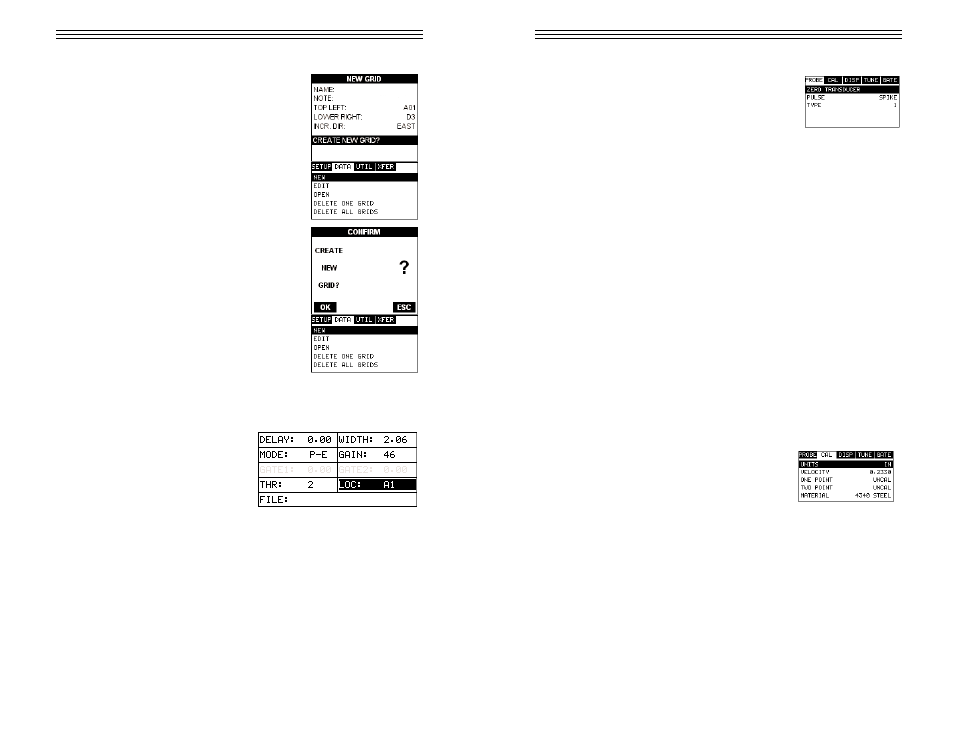
Saving the Grid
Once all the parameters are set, the user has the
option of saving or canceling the new grid.
1) Use the UP and DOWN arrow keys to scroll
through the new Grid List Items until CREATE
NEW GRID? is highlighted.
2) Press the ENTER key to accept the grid
parameters, and activate the confirmation screen.
3) Press the OK key to save the New Grid, or the
ESC key to cancel the New Grid setup and return
to the DATA menu.
4) Press the MEAS key to return to the measure-
ment screen and begin storing readings.
10.3 Storing a reading
Now that a grid has been created, it’s time to make some measurements and
store the readings. The following procedures outline this process:
Storing a Reading
1) Press the MEAS key once to activate
measure menu items. Press the MEAS
key multiple times to move right and the
ESC key multiple times to move left until
the LOC cell is highlighted.
-68-