Pacemaker monitoring, And 5-lead cables for pacemaker patients – Welch Allyn 1500 Patient Monitor v.1.4.X - User Manual User Manual
Page 48
44
Monitoring and Measurements
Welch Allyn 1500 Patient Monitor
Pacemaker monitoring
3- and 5-lead cables for pacemaker patients
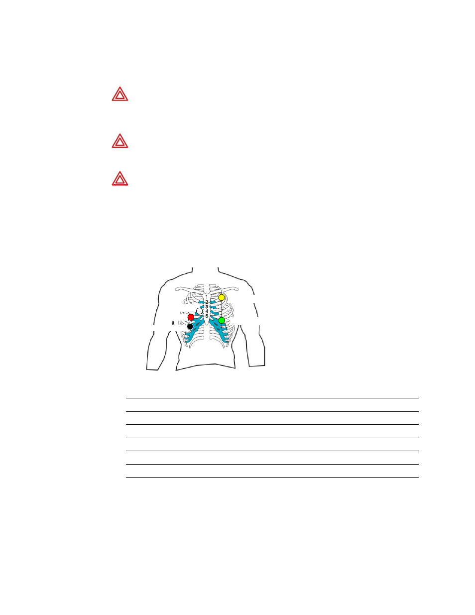
The following illustration shows the electrode placement with a 5-lead patient cable for
optimum results for patients with an implanted pacemaker.
With a 3-lead patient cable, only R, L and F are connected.
WARNING
Patients with a pacemaker must be observed continuously because
the heart rate from the pacemaker might still be registered in case of a cardiac
arrest or some arrhythmias. See specification
on page 127 for
disclosure of the pacemaker pulse rejection capability of this monitor.
WARNING
Pacemaker monitoring is not possible with ECG cables that have un-
shielded lead wires. Ensure that only shielded lead wire ECG cables are used
when monitoring patients that have a pacemaker.
WARNING
Welch Allyn recommends using an SpO
2
sensor in addition to the
ECG measurement and to set the alarm range for the peripheral pulse (PP) in the
range of the heart rate (HR), or to set the HR source in the SpO
2
menu to SpO
2
(see
IEC
AHA
Black (N)
Green (RL)
Red (R)
White (RA)
Yellow (L)
Black (LA)
Green (F)
Red (LL)
White (C)
Brown (V)
Red (R)
Green (F)
Yellow (L)
White (C)
Black (N)