3 load cells, 1 load cell input test (quick access), 2 load cell testing – Rice Lake Signal Conditioning Transmitter/Indicators User Manual
Page 7
Introduction
3
Windy Conditions - Shocks - Vibrations:
The use of weigh modules is strongly recommended for all load cells to compensate for misalignment of the
support surfaces. The system designer must ensure that the scale is protected against lateral shifting and tipping
relating to shocks and vibration, windy conditions, seismic conditions and stability of the support structure.
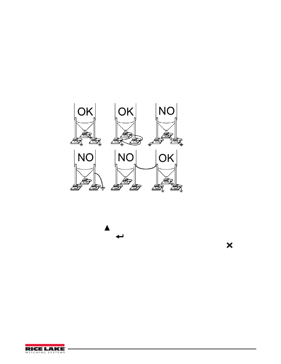
Grounding The Weighed Structure:
By means of a 10ga solid or braided wire or braided grounding strap, connect the load cell upper support plate with
the lower support plate, then connect all the lower plates to a single earth ground. Once installed electrostatic
charges accumulated are discharged to the ground without going through or damaging the load cells. Failure to
implement a proper grounding system might not affect the operation of the weighing system; this, however, does
not rule out the possibility that the load cells and connected instrument may become damaged by ESD. It is
forbidden to ensure grounding system continuity by using metal parts contained in the weighed structure.(see
Figure 1-1. Installation Recommendations
1.3
Load Cells
1.3.1 Load Cell Input Test (Quick Access)
1. From the weight display, press
for three seconds.
2. The display will read NU-CEL. Press
.
3. The response signal of the load cell is displayed, expressed in mV with four decimals. Press
three times
to exit test mode.
1.3.2 Load Cell Testing
Load Cell Resistance Measurement (Use A Digital Multimeter):
• Disconnect the load cells from the instrument and check that there is no moisture in the load cell junction box
caused by condensation or water infiltration. If so, drain the system or replace it if necessary.
• The value between the positive signal wire and the negative signal wire must be equal or similar to the one
indicated in the load cell data sheet (output resistance).
• The value between the positive excitation wire and the negative excitation wire must be equal or similar to the
one indicated in the load cell data sheet (input resistance).
• The insulation value between the shield and any other load cell wire and between any other load cell wire and
the body of the load cell must be higher than 20 Mohm (mega ohms).
Uses ground plate to
continue ground.
Uses structure to continue ground.