Step d, Step d-06 q, Step d-07 q – Losi LOSA0805 User Manual
Page 20: Rear suspension arm assembly, Sway bar assembly
15
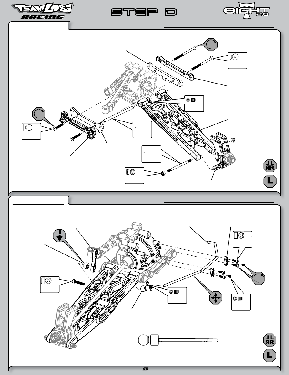
Rear Suspension Arm Assembly
STEP D-06
q
Sway Bar Assembly
STEP D-07
q
STEP D
Install the Sway Bar Ball onto the Sway Bar Wire until the
end of the wire is flush with the ball as pictured above.
5/40 x 3/4"
A6272
x2
L 5-40 x 1/4"
A6302
x 2
5-40 x 1-7/8"
A6273
x 2
4-40 x 5/8"
A6221
x 2
C 4-40 x 1/8"
A6227
x 2
2-56 x 1/4"
A6232
x 4
O 10-32 x 3/8"
A6295
x 2
4 x 66mm
A6500
x 2
Solid
5-40 x 1/8"
A6297
x 2
3.5 x 53mm
A6503
x 2
Solid
A1743
Rear Outer Hinge
Pin Brace 3.5T/3A
A4431
Rear Outer Pivot
Brace Cap
A4431
Rear Inner Pivot
Brace Cap
A1745
Rear Inner Hinge
Pin Brace
A4453
Hub Spacer .050”
A1726
Left Rear Arm
A1750
Sway Bar Link
A1750
Sway Bar Ball
A1750
Rear Sway Bar, 2.3mm
A4453
Sway Bar Mount Cap
A1750
Sway Bar Bar, Arm
See also other documents in the category Losi Hardware:
- LOSA0911 (1 page)
- LOSA1755 (1 page)
- LOSA1757 (1 page)
- LOSA1758 (1 page)
- LOSA3358 (1 page)
- LOSA3600 (2 pages)
- LOSA9155 (1 page)
- LOSA99059 (6 pages)
- LOSA99061 (4 pages)
- LOSA99062 (4 pages)
- LOSA99072 (2 pages)
- LOSA99171 (1 page)
- LOSA99171-Adendum (1 page)
- LOSA99176 (1 page)
- LOSA99181 (1 page)
- LOSB0014 (8 pages)
- LOSB0017 (10 pages)
- LOSR1002 (4 pages)
- 8IGHT Throttle/Brake Linkage (4 pages)
- 1/10 Scale 2wd Short Course Rules (1 page)
- LOSR2100 (4 pages)
- LOSB9504 (4 pages)
- LOSB0222BD (3 pages)
- Micro Brushless Conversion (14 pages)
- LOSB0882 (2 pages)
- LOSB0883v (2 pages)
- LOSB3594 (1 page)
- LOSB9400 (4 pages)
- LOSB9420 (4 pages)
- LOSB9430 (4 pages)
- LOSB9460 (4 pages)
- LOSB9464 (4 pages)
- LOSB9515 (52 pages)
- LOSB9521 (1 page)
- LOSB9524 (3 pages)
- LOSB9530 (8 pages)
- LOSB9535 (59 pages)
- LOSB9536 (47 pages)
- LOSB9500 (6 pages)
- Brushless ESC (1 page)
- LOSB9556 1/8 Xcelorin Brushless Motor Manual (5 pages)
- LOSB9557 1/8 Xcelorin ESC Manual (55 pages)
- LOSB9593 (3 pages)
- LOSB9594 (8 pages)