Losi LOSB0083 User Manual
Brake disc and pad set-up, Installing the throttle linkage
Before proceeding, become familiar with the operation of your radio system. Refer to your operation manual and become famil-
iar with the End Point Adjustment (EPA) or Travel Adjustment for throttle, brake, and all trim adjustments.
Brake Disc and Pad Set-up
Proper brake pad to disc clearance is essential for optimal
braking performance, use this method for initial set-up and
maintenance and to check the presets from the factory. Due to
normal brake wear, this setting should be checked after every
60-90 minutes of use.
1.With the radio tray powered off and the throttle servo arm
removed, move the brake linkage wires towards the engine to
the full throttle position.
2.Push the brake pads closed towards the center diff mount
by hand. The brake cams and linkage should not engage, if
they are engaged the pads will not compress all the way to the
center diff mount.
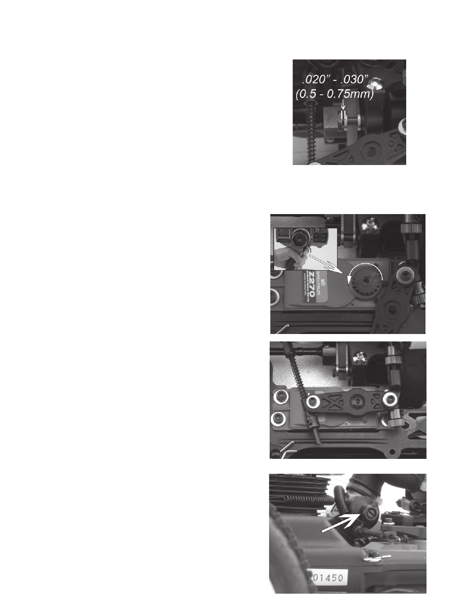
3.Using a 4-40 washer as a gauge, adjust the brake screw to
set the gap between the head of the screw and the brake pad
to .020 - .030” (0.5 - 0.75mm). The washer should ? t snug into
the gap. (Fig. 1)
NOTE: Removing the center diff assembly will make this adjus-
ment easier.
4.Repeat on all four brake screws.
Installing the Throttle Linkage
1.Turn on your transmitter. Adjust the throttle trim on the trans-
mitter to the neutral or centered position, this will allow for ? ne
adjustment later.
2. With the servos, receiver, swtich and charged receiver
battery installed and connected, turn on the radio tray. When
throttle is applied, ensure the servo is rotating in the proper
direction. (Fig.2)
NOTE: To change the servo rotation, locate the servo revers-
ing function on your transmitter and switch the direction of the
servo.
3.Select a servo adapter that matches the number of splines
on your servo (refer to your owners guide).
4.Place the servo arm adaptor onto the output shaft of the
servo. Aligning the throttle servo arm parallel with the side of
the servo case, place the arm onto the splines of the adaptor.
If there is a slight angle, use the trim adjustment on your radio
to position the arm as shown (Fig. 3). Secure the throttle servo
arm with the screw supplied with the servo.
NOTE: If the arm cannot be positioned as shown using trim ad-
justment, the angle can be changed by removing the arm and
adaptor and rotating the adaptor one spline in either direction
until the arm is positioned as shown (Fig. 3).
5.Snap the throttle linkage ballcup onto the carburetor ball.
The linkage should be level with the bottom of the chassis, and
NOT hitting the servo case. Test for free movement. If neces-
sary, rotate the ball/ring on the carburetor. (Fig. 4)
Installing and Adjusting your 8IGHT Throttle/Brake Linkage
800-0318
Fig. 1
Fig. 2
Fig. 3
Fig. 4