Losi LOSB9504 User Manual
Losi Hardware
EN
Be careful, some transmitters offer better resolution
than others. If your ESC will not respond to “Neutral”
throttle, make this setting larger.
Setting 1: Large—0.1500 ms
Setting 2: Normal—0.1000 ms (Default)
Setting 3: Small—0.0750 ms
Setting 4: Very Small—0.0500 ms
Setting 5: Smallest—0.0250 ms
7. Cutoff Voltage
Sets the voltage at which the ESC lowers or removes
power to the motor in order to either keep the battery
at a safe minimum voltage (Lithium Polymer cells) or
the radio system working reliably (NiCad/NiMH cells).
Setting 1: None
Does not cut off or limit the motor due to low
voltage. Do not use with any Lithium Polymer packs.
Applications: Any racing or bashing situation with
6–8 cell NiCad or NiMH packs.
Use this setting ONLY with NiCad or NiMH packs.
With continued driving, the radio system may
eventually cease to deliver pulses to the servo and
ESC, potentially causing the vehicle to lose control.
You will irreversibly damage Lithium Polymer packs
with this setting.
Setting 2: Auto-LiPo (Default)
This setting automatically detects the number of LiPo
cells you have plugged in. It will automatically set the
cut-off to 3.2 volts per cell. It will beep the number
of cells in your LiPo pack between the initialization
tones and the arming tones on initial power up the
controller.
Setting 3: 5V
Cuts off/limits the motor speed/acceleration when the
pack gets down to 5 volts. A good setting for racing
or bashing in any vehicle using 8–12 NiMH or NiCad
packs.
Setting 4: 6V
Cuts off/limits acceleration when the pack gets down
to 6 volts.
A MUST USE setting for 2-cell (7.4V) Lithium Polymer
packs. You will irreversibly damage your packs using
a lower cutoff voltage.
Setting 5: 9V
Cuts off/limits acceleration when the pack gets down
to 9 volts.
A MUST USE setting for 3-cell (11.1V) Lithium
Polymer packs. You will irreversibly damage your
packs using a lower cutoff voltage.
Setting 6: 12V
Cuts off/limits acceleration when the pack gets down
to 12 volts.
A MUST USE setting for 4-cell (14.8V) Lithium
Polymer packs. You will irreversibly damage your
packs using a lower cutoff voltage. Use of a 4-cell
LiPo pack is covered under warranty ONLY on
Monster Max ESCs.
8. Motor Timing
Advancing the timing on an electric motor can have
varying effects. Lowering the timing advance will
reduce the amp draw, increase runtime, reduce motor/
battery temperature, and may slightly reduce top speed
and punch. Raising the timing advance will increase
amp draw, decrease runtime, increase motor/battery
temperature, and may slightly increase top speed and
punch.
If you are after maximum top speed, it’s better to “gear
up” to get it rather than advance the timing too far.
For brushed motors, always keep this setting on
NORMAL and use the end bell of the motor to “tweak”
it to max RPM per the motor’s instructions.
Setting 1: Lowest
A maximum efficiency setting giving long runtimes
and cooler motor temps. Very useful with high Kv
(low turn) motors to increase motor life and reduce
motor/battery temperatures.
Setting 2: Normal (Default)
The best mix of speed, punch and efficiency for all
motors.
Setting 3: Highest
Increases amp draw, reduces runtimes, increases
motor/battery temperatures and may increase top
speed/punch slightly.
Use with care and monitor motor and battery temps
often. DO NOT use any setting above “normal” with
6000Kv or higher motors.
9. Motor Type
This setting sets which type of motor you will be
using with the Losi ESC. The ESC may be damaged if
this setting does not match the motor type/hook-up
method in the car, and this damage is not covered
under warranty.
Setting 1: Brushless (Default)
(See Brushless Motor Setup section) Uses all three of
the ESC motor wires connected to all three of the
brushless motor wires. If the motor spins the wrong
way with forward throttle, swap any two of the wires
to get the correct direction.
Setting 2: Brushed Reversing
(See Reversing Brushed Motor Setup section) Uses the
Red and Black ESC motor wires to connect to the (+)
and (-) side of the brushed motor. If the motor spins
in the wrong direction with forward throttle, reverse
the motor wires for correct motor direction.
Setting 3: Brushed High Power
(See High Power Brushed Motor Setup section)
Connect all three of the ESC motor wires to the
negative (-) side of the motor. You can either use a
“Y” harness from the ESC battery input positive wire
to connect to both the battery and the positive side
of the motor, or use a single wire from the positive
ESC input to the positive battery pole and then
continue to the positive (+) side of the motor.
Troubleshooting
If you’re still having difficulties with your Losi ESC after
trying the suggestions offered here, please contact Losi
Service Center at the e-mail or phone number listed
below.
Problem: My Losi ESC may or may not arm, but it will
not calibrate to my transmitter.
Solution: Most calibration issues can be solved by
changing settings on the transmitter. Make sure you
have both your throttle and brake endpoints (called
EPA or ATV on your radio) on the throttle channel out
to between 100 to 120%. Make sure if you have a
Futaba or Futaba made transmitter to have the throttle
channel set to the reversed position.
Problem: My ESC calibrates for the full throttle and
full brake positions, but won’t calibrate to the neutral
throttle position (yellow LED keeps flashing).
Solution: Try moving the throttle trim one way, then
the other (usually towards the throttle side is best). If
your transmitter has a 50/50 and 70/30 setting for the
throttle, set it for 50/50 and retry calibration. Also, if
you have changed the dead band to a narrower band
you may want to try going back to the “normal”
setting.
Problem: My vehicle acts like it has “turbo lag” (poor
acceleration/punch for the first few feet or yards, and
then it “kicks in”).
Solution: Make sure you’re using high quality batteries
and a battery connector capable of high amp flow
(40–100 amps). This behavior is very typical of a battery
pack that is having difficulty providing the power your
vehicle/system requires for top performance.
Use copper bars to connect cells rather than welded
tabs. Copper bars have a much lower resistance.
Problem: My battery pack is plugged into the ESC and
nothing is working - no steering and no throttle.
Solution: Make sure the ESC’s receiver plug is plugged
into channel 2 on the receiver, and that it’s plugged in
with the correct orientation. Double check your solder
connections on the battery plug, and make sure the
battery is showing good voltage.
LIMITED WARRANTY
What this Warranty Covers
Horizon Hobby, Inc. (“Horizon”) warrants to the
original purchaser that the product purchased (the
"Product") will be free from defects in materials and
workmanship at the date of purchase.
What is Not Covered
This warranty is not transferable and does not cover
(i) cosmetic damage, (ii) damage due to acts of God,
accident, misuse, abuse, negligence, commercial use,
or due to improper use, installation, operation or
maintenance, (iii) modification of or to any part of
the Product, (iv) attempted service by anyone other
than a Horizon Hobby authorized service center, or (v)
Products not purchased from an authorized Horizon
dealer.
OTHER THAN THE EXPRESS WARRANTY ABOVE,
HORIZON MAKES NO OTHER WARRANTY OR
REPRESENTATION, AND HEREBY DISCLAIMS ANY AND
ALL IMPLIED WARRANTIES, INCLUDING, WITHOUT
LIMITATION, THE IMPLIED WARRANTIES OF NON-
INFRINGEMENT, MERCHANTABILITY AND FITNESS
FOR A PARTICULAR PURPOSE. THE PURCHASER
ACKNOWLEDGES THAT THEY ALONE HAVE
DETERMINED THAT THE PRODUCT WILL SUITABLY
MEET THE REQUIREMENTS OF THE PURCHASER’S
INTENDED USE.
Purchaser’s Remedy
Horizon’s sole obligation and purchaser’s sole and
exclusive remedy shall be that Horizon will, at its
option, either (i) service, or (ii) replace, any Product
determined by Horizon to be defective. Horizon
reserves the right to inspect any and all Product(s)
involved in a warranty claim. Service or replacement
decisions are at the sole discretion of Horizon. Proof of
purchase is required for all warranty claims. SERVICE OR
REPLACEMENT AS PROVIDED UNDER THIS WARRANTY
IS THE PURCHASER’S SOLE AND EXCLUSIVE REMEDY.
Limitation of Liability
HORIZON SHALL NOT BE LIABLE FOR SPECIAL,
INDIRECT, INCIDENTAL OR CONSEQUENTIAL
DAMAGES, LOSS OF PROFITS OR PRODUCTION OR
COMMERCIAL LOSS IN ANY WAY, REGARDLESS OF
WHETHER SUCH CLAIM IS BASED IN CONTRACT,
WARRANTY, TORT, NEGLIGENCE, STRICT LIABILITY OR
ANY OTHER THEORY OF LIABILITY, EVEN IF HORIZON
HAS BEEN ADVISED OF THE POSSIBILITY OF SUCH
DAMAGES. Further, in no event shall the liability of
Horizon exceed the individual price of the Product on
which liability is asserted. As Horizon has no control
over use, setup, final assembly, modification or misuse,
no liability shall be assumed nor accepted for any
resulting damage or injury. By the act of use, setup or
assembly, the user accepts all resulting liability. If you
as the purchaser or user are not prepared to accept
the liability associated with the use of the Product,
purchaser is advised to return the Product immediately
in new and unused condition to the place of purchase.
Law
These terms are governed by Illinois law (without
regard to conflict of law principals). This warranty gives
you specific legal rights, and you may also have other
rights which vary from state to state. Horizon reserves
the right to change or modify this warranty at any time
without notice.
WARRANTY SERVICES
Questions, Assistance, and Services
Your local hobby store and/or place of purchase
cannot provide warranty support or service. Once
assembly, setup or use of the Product has been
started, you must contact your local distributor
or Horizon directly. This will enable Horizon to
better answer your questions and service you in
the event that you may need any assistance. For
questions or assistance, please direct your email
to [email protected], or call
877.504.0233 toll free to speak to a Product
Support representative. You may also find
information on our website at
www.horizonhobby.com.
Inspection or Services
If this Product needs to be inspected or serviced,
please use the Horizon Online Service Request
submission process found on our website or
call Horizon to obtain a Return Merchandise
Authorization (RMA) number. Pack the Product
securely using a shipping carton. Please note
that original boxes may be included, but are not
designed to withstand the rigors of shipping
without additional protection. Ship via a carrier
that provides tracking and insurance for lost or
damaged parcels, as Horizon is not responsible for
merchandise until it arrives and is accepted at our
facility. An Online Service Request is available at
http://www.horizonhobby.com under the Support
tab. If you do not have internet access, please
contact Horizon Product Support to obtain a RMA
number along with instructions for submitting
your product for service. When calling Horizon,
you will be asked to provide your complete name,
street address, email address and phone number
where you can be reached during business hours.
When sending product into Horizon, please
include your RMA number, a list of the included
items, and a brief summary of the problem.
A copy of your original sales receipt must be
included for warranty consideration. Be sure your
name, address, and RMA number are clearly
written on the outside of the shipping carton.
NoTICE: Do not ship LiPo batteries to
Horizon. If you have any issue with a LiPo
battery, please contact the appropriate
Horizon Product Support office.
Warranty Requirements
For Warranty consideration, you must include
your original sales receipt verifying the proof-of-
purchase date. Provided warranty conditions have
been met, your Product will be serviced or replaced free
of charge. Service or replacement decisions are at the
sole discretion of Horizon.
Non-Warranty Service
Should your service not be covered by warranty
service will be completed and payment will be
required without notification or estimate of the
expense unless the expense exceeds 50% of the
retail purchase cost. By submitting the item for
service you are agreeing to payment of the service
without notification. Service estimates are available
upon request. You must include this request with
your item submitted for service. Non-warranty service
estimates will be billed a minimum of ½ hour of labor.
In addition you will be billed for return freight. Horizon
accepts money orders and cashiers checks, as well
as Visa, MasterCard, American Express, and Discover
cards. By submitting any item to Horizon for service,
you are agreeing to Horizon’s Terms and Conditions
found on our website http://www.horizonhobby.com/
Service/Request/.
Compliance Information for the
European Union
Declaration of Conformity
(in accordance with ISO/IEC 17050-1)
No. HH2011110302
Product(s):
LOS TEN-SCTE RTR ESC
Item Number(s):
LOSB9504
The object of declaration described above is in
conformity with the requirements of the specifications
listed below, following the provisions of the European
EMC Directive 2004/108/EC:
EN61000-6-1:2007
EN61000-6-3:2007
Signed for and on behalf of:
Horizon Hobby, Inc.
Champaign, IL USA
Nov 3, 2011
Instructions for Disposal of WEEE
by Users in the European Union
This product must not be disposed of with
other waste. Instead, it is the user’s responsibility to
dispose of their waste equipment by handing it over
to a designated collection point for the recycling of
waste electrical and electronic equipment. The separate
collection and recycling of your waste equipment at the
time of disposal will help to conserve natural resources
and ensure that it is recycled in a manner that
protects human health and the environment. For more
information about where you can drop off your waste
equipment for recycling, please contact your local city
office, your household waste disposal service or where
you purchased the product.
LoSB9504 MSC-MXPRo BRUSHLESS ESC
NoTICE
All instructions, warranties and other collateral
documents are subject to change at the sole discretion
of Horizon Hobby, Inc. For up-to-date product
literature, visit www.horizonhobby.com and click on
the support tab for this product.
Meaning of Special Language
The following terms are used throughout the product
literature to indicate various levels of potential harm
when operating this product:
NoTICE: Procedures, which if not properly followed,
create a possibility of physical property damage AND
little or no possibility of injury.
CAUTIoN: Procedures, which if not properly followed,
create the probability of physical property damage
AND a possibility of serious injury.
WARNING: Procedures, which if not properly
followed, create the probability of property damage,
collateral damage, and serious injury OR create a high
probability of superficial injury.
WARNING: Read the ENTIRE instruction manual
to become familiar with the features of the
product before operating. Failure to operate the product
correctly can result in damage to the product, personal
property and cause serious injury.
This is a sophisticated hobby product and NOT a toy.
It must be operated with caution and common sense
and requires some basic mechanical ability. Failure to
operate this Product in a safe and responsible manner
could result in injury or damage to the product or
other property. This product is not intended for use by
children without direct adult supervision. Do not attempt
disassembly, use with incompatible components or
augment product in any way without the approval of
Horizon Hobby, Inc. This manual contains instructions
for safety, operation and maintenance. It is essential
to read and follow all the instructions and warnings in
the manual, prior to assembly, setup or use, in order to
operate correctly and avoid damage or serious injury.
Age Recommendation
• Not for Children under 14 years.
This is not a toy.
Features
• Easy calibration
• Compact footprint
• Pre-wired with EC3
™
battery plug
• Low-Voltage Cutoff for 2S 7.4V Li-Po,
Ni-MH and Ni-Cd battery packs
• Forward/Brake function for racing and Forward/
Brake/Reverse function for sport driving
• Adjustable drag brake
• ROAR Legal for Non-Timing Spec Classes
Specifications
Motor Type
Sensored and Sensorless
Brushless
Low-Voltage Cutoff Automatic Detection
Input Voltage
LiPo 2–4S or 8.4V–16.8V
Full on Resistance .0018 Ohm
Motor Limit
4.5T 550 Sensored
Motor output
13AWG
Lead AWG
Motor Connector
4.0mm Bullet Plug
Battery Input
13AWG
Lead AWG
Battery Connector EC3™
Type
Dimensions
45.5 x 36.5 x 21.5mm
(1.79 x 1.44 x .85 in)
Weight
81 g (2.8 oz)
(without wires)
BEC output
5.5–7.0V
Power Wiring
Your ESC has motor connectors on the motor wires and
the battery input wires.
Proper polarity is essential. Make absolutely certain that
positive (+) connects to positive (+), and negative (-)
connects to negative (-) when you plug in your battery. If
reverse polarity is applied to your ESC from the battery,
it WILL damage your ESC. This WILL NOT be covered
under warranty.
Connections
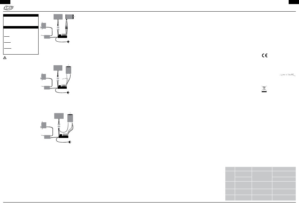
Brushless Motor Wiring
For brushless motor connection, the three wires from
the ESC to the motor have no polarity. Connect the red,
white and black motor wires to the three wires coming
from the motor. If you are using a motor other than a
Losi LOSB9444 motor, you may need to either solder on
matching male bullet plugs to your motor, or solder the
ESC wires directly to the motor wires.
Since there is no polarity on the three ESC-to-motor
wires, do not worry about how you connect them
initially. You may find it necessary to swap two wires if
the motor runs in reverse. This will be explained later.
Connect
controller
and motor
using
supplied
connectors
Connect
to throttle
channel
Steering Servo
in CH1
Losi ESC
in CH2
Receiver
Battery
Pack
Use a high quality
connector only
On/Off
Switch
Steering
Servo
Brushless
Motor
MSC-MXPRO ESC
Brushed Motor Wiring
Reversing Brushed Motor Mode:
Use this mode if you wish to use reverse. Use only
the red and black motor wires from the ESC. In most
applications, the red wire from the ESC will connect to
the red wire (or positive (+) side hood) on your motor,
and the black wire to the black wire (or negative (–) side
hood) of the motor. The white motor wire is not used.
After calibration (explained below), you may need to
swap the two motor wires to get the wheels to spin in
the desired direction.
Black ESC
motor wire
to Motor (-)
White motor
wire not used
Red ESC
motor wire
to Motor (+)
Connect
to throttle
channel
Steering Servo
in CH1
Losi ESC
in CH2
Receiver
Battery
Pack
Use a high quality
connector only
On/Off
Switch
Steering
Servo
MSC-MXPRO ESC
Brushed
Motor
High Power Brushed Motor Mode:
(See Figure 3: High Power Brushed Motor Setup)
Connect all three of the ESC motor wires to the negative
(-) side of the motor. You can either use a “Y” harness
from the ESC battery input positive wire to connect to
both the battery and the positive side of the motor,
or use a single wire from the positive ESC input to the
positive battery pole and then continue to the positive
(+) side of the motor.
Battery (+)
to
Motor (+) Motor
Tab
(+)
Motor
Tab
(-)
All ESC
motor wires
to Motor (-)
Connect to
throttle
channel
Steering Servo
in CH1
Losi ESC
in CH2
Receiver
Battery
Pack
Use a high quality
connector only
On/Off
Switch
Steering
Servo
Brushed
Motor
MSC-MXPRO ESC
Radio Connection
Your Losi ESC plugs into the throttle channel of your
receiver. This is usually channel 2. Your Losi ESC provides
5 volts to the receiver to power the receiver and the
steering servo. No separate receiver battery is needed to
power the radio system.
Losi ESC receiver plugs are made to be used with any
receiver, so you will need to make sure the polarity is
correct. The signal wire is orange, the positive wire is red
and the negative is brown. Some radio systems use the
white for signal, red for positive and black for negative
color scheme. Check your receiver documentation for
correct connection polarity if it’s not marked. (Most
receivers use negative to the outside of the case and
signal towards the inside of the case.)
ESC Setup
ESC/Radio Calibration
Individual transmitter’s signals for neutral, full and full
brake vary. You must calibrate the ESC so that it will
operate most effectively with your transmitter. Anytime
the ESC is powered up with a new transmitter or with
different throttle channel settings, it will need to be
calibrated to “know” what the transmitter’s throttle
settings are. It will also need to be calibrated after
updating with new software via Castle Link.
If you are using a Futaba or Futaba OEM brand
transmitter, you will need to set the transmitter’s throttle
channel direction to the REVERSE (Rev) position. This is
either an external micro switch on the transmitter or an
option available within the computer programming of
the transmitter’s throttle channel.
Please start by zeroing out any throttle trim that you may
have set in your transmitter.
Don’t plug in the battery yet. Make sure that the battery
polarity and input polarity on the ESC are correct. Check
the on/off switch of the Losi ESC to make sure that it is
in the OFF position (“ON” is marked in small letters on
one side).
We recommend removing your pinion gear before
calibration as a safety precaution.
How to Calibrate the ESC
STEP 1: Start with the transmitter ON and the ESC
switched OFF and not connected to the battery.
STEP 2: Plug a battery into your Losi ESC.
STEP 3: Hold full throttle on the transmitter and turn
the ESC’s switch ON. Keep holding full throttle on the
transmitter. If all your connections are correct, you will
hear one multi-toned initialization “ring” from the motor
(all tones are played by the ESC vibrating the motor).
STEP 4: After a second or two, the green LED on the
ESC will blink rapidly and the motor will “ring” 4 times
rapidly in a row (accepting the full throttle endpoint).
After the green LED flashes and tones, the red LED on
the ESC will blink. At this point, the full throttle endpoint
has been set within the ESC and now it’s looking for the
full brake endpoint (red LED blinking).
STEP 5: Move the throttle trigger to the full brake
position and hold full brake. After a few seconds, the
red LED on the ESC will flash and ring 4 times rapidly
(accepting full brake endpoint).
STEP 6: After accepting the full brake endpoint, the
yellow LED on the ESC will blink. Relax the trigger to the
neutral position. The ESC will now ring 4 times and flash
the yellow LED rapidly to accept the neutral position.
After accepting the neutral position, the ESC will ring
twice and all the LEDs will flash. This is the arming tone
and LED indication that the ESC is now ARMED and the
car will respond to throttle inputs from your transmitter.
From this point on, when you connect the battery and
turn the switch on, the ESC will give the initialization
tone and flash. Then the arming tone will ring a second
or two later. If the ESC is programmed for the Auto-LiPo
setting, it will beep the number of cells in your LiPo pack
between the initialization tones and the arming tones.
After the arming tone plays, the ESC is ACTIVE and will
respond to throttle application.
If you have problems calibrating your transmitter with
the Losi ESC, please contact the appropriate Horizon
Hobby Service Center. Once you are calibrated and
armed, do one last check before going out and
experiencing the Losi brushless difference. Slowly
advance the throttle and check the rotation direction of
the motor and the color of the LEDs on the ESC. If the
motor is spinning in the right direction and the GREEN
LED is blinking, then you are ready for a test run before
going into the settings of the ESC. If the ESC displays
the green LED with throttle but the wheels spin in the
wrong direction, you’ll need to switch any two of the
motor wires (example: switch from red to red and black
to black to red to black and black to red).
Manual Programming
Follow these steps to change settings on the ESC
without a computer.
Remove your pinion gear before calibration and manual
programming as a safety precaution.
STEP 1: Start with the transmitter ON and the ESC
switched OFF and not connected to the battery.
STEP 2: Plug a battery into the ESC. Hold full throttle on
the transmitter and turn the ESC switch ON. After a few
seconds you will hear four rings signaling full throttle
calibration. Continue holding full throttle. After a few
more seconds, you will hear another four rings. After the
second group of four rings, relax the throttle to neutral.
If you have successfully entered programming mode, the
ESC will beep twice, pause, and repeat the two beeps.
STEP 3: The programming sequence is always presented
in sequential order and always starts with the first
setting (Reverse Lockout) within the first section (Reverse
Type). The first beep(s) signifies which section of the
programming you are in and the second beep(s) signifies
which setting is waiting for a “yes” or “no” answer.
As you cycle through the options, you will need to
answer “yes” by holding full throttle or answer “no”
by holding full brake until the ESC accepts your answer
by beeping rapidly. Once an answer has been accepted,
relax the throttle back to neutral for the next question.
After a “no” answer is accepted, the ESC will present
you with the next option in that section. After a “yes”
answer is accepted, the ESC skips to the first option in
the next section.
Settings & Explanations
The ESC is extremely flexible and may be “tuned” like
any other part of your car or truck. The following section
explains all the settings available to you via manual
programming and what each one does to change the
reactions of the ESC in order to tune it to your specific
preferences.
1. Brake/Reverse Type
Sets whether reverse is enabled and how it can be
accessed.
Setting 1: Reverse Lockout (Default)
This setting allows the use of reverse only after the
ESC senses two seconds of neutral throttle. Use it for
race practice sessions and bashing, but check with
your race director to see if this setting is allowed for
actual racing.
Setting 2: Forward/Brake Only
Use this setting for actual sanctioned racing events.
Reverse cannot be accessed under any circumstances
with this setting.
Setting 3: Forward/Brake/Reverse
Reverse or forward is accessible at any time after
the ESC brakes to zero motor RPM (if the vehicle is
moving).
2. Brake Amount
Sets what percentage of available braking power is
applied with full brake.
Setting 1: 25% Power
Allows only 25% of available braking power at full
brake.
Setting 2: 50% Power (Default)
Allows only 50% of available braking power at full
brake.
Setting 3: 75% Power
Allows 75% of available braking power at full brake.
Setting 4: 100% Power
Allows all available braking power at full brake.
3. Reverse Amount
Sets how much power will be applied in the reverse
direction, if reverse is enabled.
Setting 1: 25% Power
Allows only 25% power in reverse.
Setting 2: 50% Power (Default)
Allows only 50% power in reverse.
Setting 3: 75% Power
Allows only 75% power in reverse.
Setting 4: 100% Power
Allows 100% power in reverse.
4. Punch/Traction Control
This setting controls how fast the throttle position within
the ESC can be changed over time. This smoothes high
power starts and limits punch somewhat. As explained
previously, acceleration is a matter of battery capability,
but you may not want 100% of what the battery can
deliver in every situation.
This setting is crucial to drag racing as it can be used as
a “traction control” to match traction conditions.
The lower the setting, the less throttle change limiting
there is. For pure burnout and wheelie action, use
a very low setting or the disabled setting. For softer
acceleration or for a low-grip surface, raise it up to a
higher setting.
Setting 1: High
Very limited acceleration. Good for 2WD vehicles on
hard dirt, or for general bashing when you want to be
gentle on the transmission.
Setting 2: Medium
Medium acceleration limiting. Good for 2WD vehicles
on soft dirt, and 4WD vehicles on hard dirt.
Setting 3: Low
Light acceleration limiting. Good for 4WD vehicles on
soft dirt.
Setting 4: Lowest
Very light acceleration limiting. Good for most
situations including 4WD vehicles on dirt and asphalt,
and 2WD vehicles on asphalt.
Setting 5: Disabled (Default)
Acceleration is only limited by battery ability. This
setting is good for 4WD sedans on carpet, high
traction drag racing, or bashing where unlimited
wheelie power is desired.
5. Drag Brake
Sets the amount of drag brake applied at neutral throttle
to simulate the braking effect of a neutral brushed
motor while coasting.
Setting 1: Drag Brake OFF (Default)
Vehicle will coast with almost no resistance from the
motor at neutral throttle.
Setting 2: Drag Brake 10%
Low amount of braking effect from the motor at
neutral throttle.
Setting 3: Drag Brake 20%
More braking effect from the motor at neutral throttle.
Setting 4: Drag Brake 30%
Fairly high braking effect from the motor at neutral
throttle.
Setting 5: Drag Brake 40%
High braking effect from the motor at neutral throttle.
6. Dead Band
You may adjust the neutral throttle “width” of the
controller with this setting. Smaller values make the
controller enter forward or brake/reverse with a smaller
movement of your throttle trigger for finer control.
Created: 9/2011 33126
EN
©2011 Horizon Hobby, Inc. Losi and EC3 are trademarks or registered trademarks of Horizon Hobby, Inc. Futaba is a registered trademark of Futaba Denshi Kogyo Kabushiki Kaisha Corporation of Japan.
Contact Information
Country of
Purchase
Horizon Hobby
Address
Phone Number/Email Address
United States
of America
Horizon Service Center
(Electronics and engines)
4105 Fieldstone Rd
Champaign, Illinois
61822 USA
877-504-0233
Online Repair Request visit:
www.horizonhobby.com/service
Horizon Product Support
(All other products)
877-504-0233
[email protected]
United
Kingdom
Horizon Hobby Limited
Units 1-4 Ployters Rd
Staple Tye, Harlow, Essex
CM18 7NS
United Kingdom
+44 (0) 1279 641 097
[email protected]
Germany
Horizon Technischer
Service
Christian-Junge-Str. 1
25337 Elmshorn, Germany
+04121 2655 100
[email protected]
France
Horizon Hobby SAS
14 Rue Gustave Eiffel
Zone d’Activité du Réveil Matin
91230 Montgeron
+33 (0) 1 60 47 44 70
[email protected]
Steven A. Hall
Vice President
International Operations and
Risk Management
Horizon Hobby, Inc.