Step b, Step b-08 q, Step b-09 q – Losi LOSA0805 User Manual
Page 11: Sway bar assembly, Tie rod/shock tower assembly
6
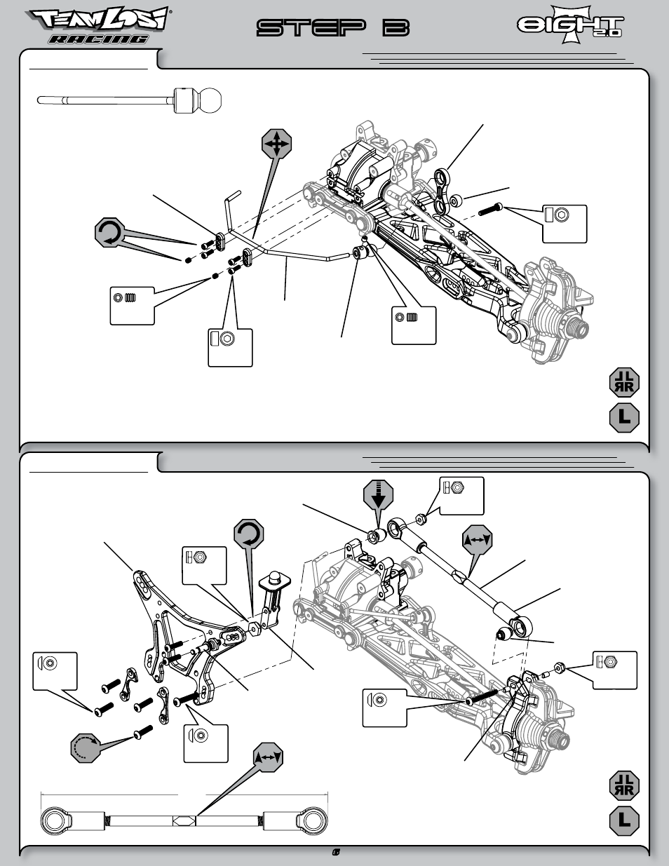
STEP B
Sway Bar Assembly
STEP B-08
q
Tie Rod/Shock Tower Assembly
STEP B-09
q
142 50
Install the Sway Bar Ball onto the Sway Bar Wire until the
end of the wire is flush with the ball as pictured above.
Be sure to install the assembled Tie
Rod onto the car with the groove
(next to the center square section)
on the driver’s left side for easier
adjustment later.
2-56 x 1/4"
A6232
x 4
C 4-40 x 1/8"
A6227
x 2
4-40 x 5/8"
A6221
x 2
L 5-40 x 1/4"
A6302
x 2
L 5-40 x 1/4"
A6302
x 2
L 8-32 x 11/32"
A6311
x 2
5-40 x 1/2"
A6278
x 4
5-40 x 3/4"
A6279
x 2
5-40 x 1"
A6280
x 1
C 5-40 x 1/8"
A6228
x 2
A1750
Front Sway Bar
A1750
Sway Bar Ball
A5438
Shock Standoff
A4433
Front Body Mount
A1712
Front Shock Tower
A6048
Suspension Ball,
Flanged
A6546
5 x 107mm Turnbuckle
A6047
Rod End
A6049
Suspension Ball
A6057
Camber Standoff
A4453
Sway Bar Mount
Cap
A1750
Sway Bar Link
A1750
Sway Bar Ball
- LOSA0911 (1 page)
- LOSA1755 (1 page)
- LOSA1757 (1 page)
- LOSA1758 (1 page)
- LOSA3358 (1 page)
- LOSA3600 (2 pages)
- LOSA9155 (1 page)
- LOSA99059 (6 pages)
- LOSA99061 (4 pages)
- LOSA99062 (4 pages)
- LOSA99072 (2 pages)
- LOSA99171 (1 page)
- LOSA99171-Adendum (1 page)
- LOSA99176 (1 page)
- LOSA99181 (1 page)
- LOSB0014 (8 pages)
- LOSB0017 (10 pages)
- LOSR1002 (4 pages)
- 8IGHT Throttle/Brake Linkage (4 pages)
- 1/10 Scale 2wd Short Course Rules (1 page)
- LOSR2100 (4 pages)
- LOSB9504 (4 pages)
- LOSB0222BD (3 pages)
- Micro Brushless Conversion (14 pages)
- LOSB0882 (2 pages)
- LOSB0883v (2 pages)
- LOSB3594 (1 page)
- LOSB9400 (4 pages)
- LOSB9420 (4 pages)
- LOSB9430 (4 pages)
- LOSB9460 (4 pages)
- LOSB9464 (4 pages)
- LOSB9515 (52 pages)
- LOSB9521 (1 page)
- LOSB9524 (3 pages)
- LOSB9530 (8 pages)
- LOSB9535 (59 pages)
- LOSB9536 (47 pages)
- LOSB9500 (6 pages)
- Brushless ESC (1 page)
- LOSB9556 1/8 Xcelorin Brushless Motor Manual (5 pages)
- LOSB9557 1/8 Xcelorin ESC Manual (55 pages)
- LOSB9593 (3 pages)
- LOSB9594 (8 pages)