3 quick reference sheet, Figure 3-8: quick reference sheet, Jumper settings – Kontron KTC5520-EATX User Manual
Page 37: Default setting)
21
www.kontron.com
3.3
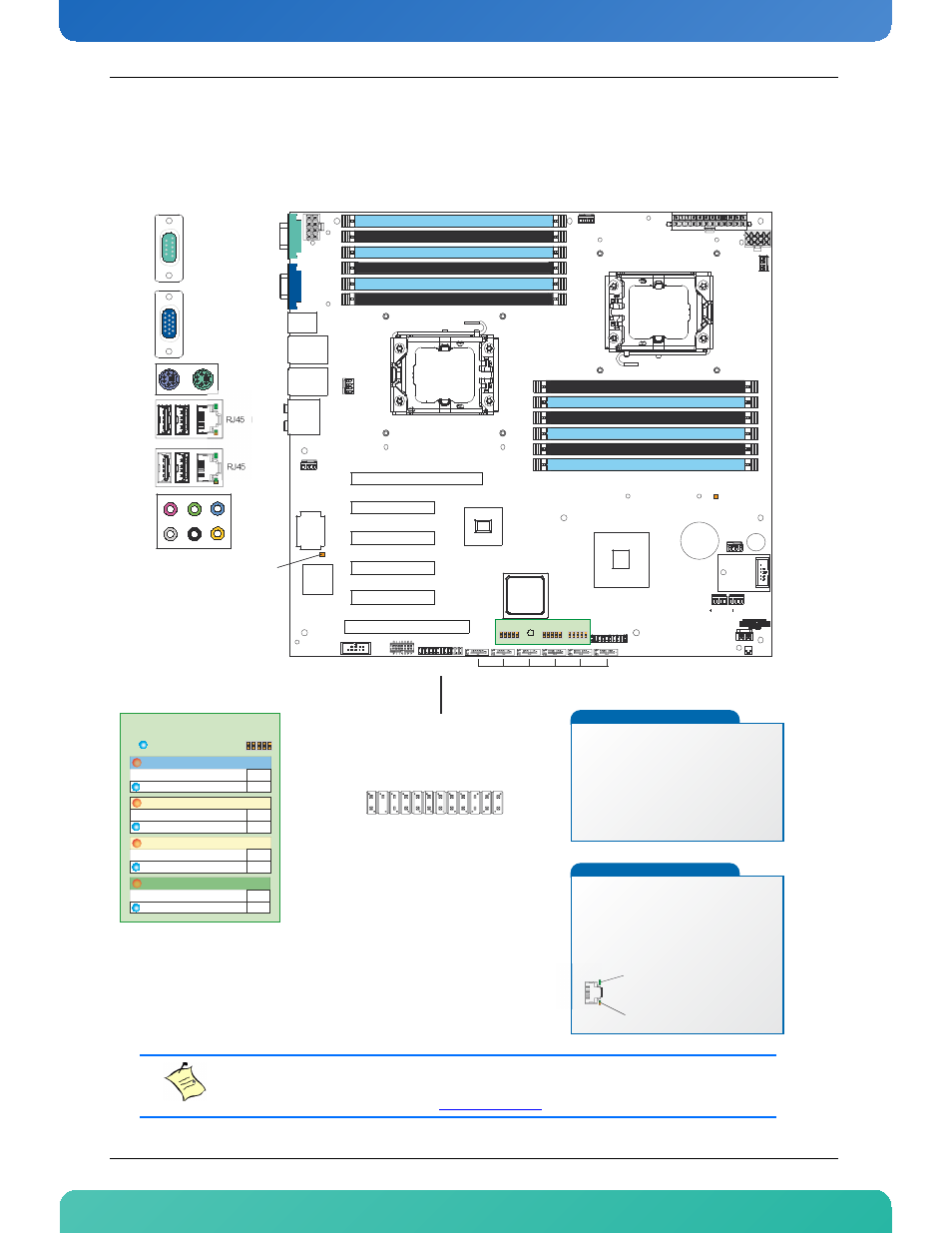
Quick Reference Sheet
Figure 3-8: Quick Reference Sheet
Note:
A soft copy can be accessed through the Web Management Interface. The latest version is always
available from the Kontron web site at
CPU 1
CPU 0
Audio
RJ45 LAN1
USB
RJ45 LAN2
USB
PS2 kbd
mouse
VGA
Serial
CPU1 Fan
CPU0 Fan
EATX POWER
EATX 12V
EATX 12V
Battery
PCI 32b / 33MHz
PCI Express Gen1 x4
PCI Express Gen2 x8
PCI Express Gen2 x8
PCI Express Gen2 x8
PCI Express Gen2 x8
Super
I/O
USB
FWM
MEZZ
Front Panel
Connector
JP3
JP2
JP1
TPM
Header
Intrusion
Connector
POST Codes
AUX Connector
ICH10
i82576
i5520
Sys2
Fan
Sys1
Fan
Mem0
Fan
Mem1
Fan
Sys3
Fan
PWR LED +
PWR LED -
HDD LED +
HDD LED -
PWR SW
GND
Reset SW
GND
NIC#1 LED +
NIC#1 LED -
NIC#2 LED +
NIC#2 LED -
SYS ID LED + (Not Used)
SYS ID LED - (Not Used)
SYS Fault LED1 - (Not Used)
SYS Fault LED2 - (Not Used)
SMBus SDA(Not Used)
SMBus SCL(Not Used)
Chassis Intrusion
Front Panel Power
Serial
VGA
USB
USB
RJ45 LAN 2
RJ45 LAN1
Mouse
Keyboard
S/PDIF In
Line
S/PDIF Out
Center/LFE
Front
Rear
Mic In
Side
Speaker
Slot 1
Slot 2
Slot 3
Slot 4
Slot 5
Slot 6
USB / USB Flash
in
out
Disable BMC Operation
Normal Operation
in
out
Clear CMOS in Flash
Normal Operation
in
out
Disabled (No KVM function)
Normal Operation
in
out
Protected
Not Protected
AST
2050
SATA
JUMPER SETTINGS
( Default Setting)
JP3 (7-8) Onboard Video
JP2 (1-2) BMC Disabled
JP2 (9-10) Clear CMOS in Flash
JP1 (7-8) Firmware Write Protect
1
1
1
1
0
1
2
3
4
5
SYS_ID_SW (Not Used)
NMI_CPU_SW (Not Used)
IOH
DDR 3 ECC Registered Channel 2 Slot 0
DDR 3 ECC Registered Channel 1 Slot 0
DDR 3 ECC Registered Channel 0 Slot 0
Fill First
Fill First
Fill First
DDR 3 ECC Registered Channel 2 Slot 1
DDR 3 ECC Registered Channel 1 Slot 1
DDR 3 ECC Registered Channel 0 Slot 1
Fill Second
Fill Second
Fill Second
DDR 3 ECC Registered Channel 0 Slot 0
DDR 3 ECC Registered Channel 1 Slot 0
DDR 3 ECC Registered Channel 2 Slot 0
Fill First
Fill First
Fill First
DDR 3 ECC Registered Channel 0 Slot 1
DDR 3 ECC Registered Channel 1 Slot 1
DDR 3 ECC Registered Channel 2 Slot 1
Fill Second
Fill Second
Fill Second
5V LED
AST2050
Hearthbeat
LED
LEDs Significations
5V LED (Amber)
On : 5V power is present onboard
Off : 5V power is not present
AST2050 Hearthbeat LED (Amber)
Blink : Management Controller is working
Off : Management Controller is not working
RJ45 Connectors LED
Software Startup
Obtaining / Configuring the IP address:
- Enter in the BIOS Setup Menu.
- Go to LAN Configuration Menu. This menu is located under
«System Management»
- Set LAN channel IP Address source, IP Address, MAC Address,
Subnet Mask and if required the Gateway Address on the
corresponding menu.
Accessing Kontron Web Management Interface
- Type the IPaddress of your board in the address bar of an
Internet browser.
- User Name: admin
- Password: admin
Link/Act
OFF: No Link
Green: Link
Blinking: Activity
Speed
OFF: 10Mb/s
Amber: 100Mb/s
Green: 1000Mb/s