1 installing the memory, Figure 3-5: memory and cpu association, Table 3-2 memory configuration – Kontron KTC5520-EATX User Manual
Page 34: Warning
18
www.kontron.com
Table 3-2: Memory Configuration
Kontron recommends to use tested memory with this product. Thermal issues or other problems may arise if
you don’t use tested modules. At the time of publication of this user guide, the following memories (Table 3-
3) were confirmed functional with the product. As the memory market is volatile, this list is subject to
change, co
for an up to date list.
3.2.4.1
Installing the Memory
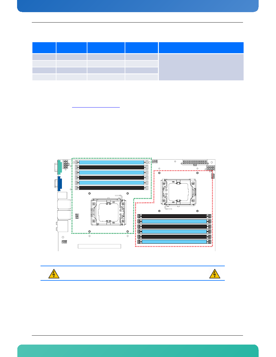
It is highly recommended to populate equally the memory for each CPU beginning with channel 0.
Figure 3-5: Memory and CPU association
DIMM Slots
per Channel
DIMM Populated
per Channel
POR Speeds
Rank per DIMM
(any combination)
Population Rules
2
1
800, 1066, 1333
SR, DR
1. Any combination of x4 and x8 RDIMMs, with
1Gb, or 2Gb DRAM density
2. Populate DIMMs starting with clock 0, furthest
from the CPU
2
1
800, 1066
QR
2
2
800, 1066
SR, DR
2
2
800
SR, DR, QR
WARNING
Unplug the power supply before manipulating the dimms
CPU 1
CPU 0
Audio
RJ45 LAN1
USB
RJ45 LAN2
USB
PS2 kbd
mouse
VGA
Serial
CPU1 Fan
CPU0 Fan
EATX POWER
EATX 12V
EATX 12V
PCI Express Gen2 x8
Mem1
Fan
Sys3
Fan
LAN 2
LAN1
Slot 6
DDR 3 ECC Registered Channel 2 Slot 0
DDR 3 ECC Registered Channel 1 Slot 0
DDR 3 ECC Registered Channel 0 Slot 0
Fill First
Fill First
Fill First
DDR 3 ECC Registered Channel 2 Slot 1
DDR 3 ECC Registered Channel 1 Slot 1
DDR 3 ECC Registered Channel 0 Slot 1
Fill Second
Fill Second
Fill Second
DDR 3 ECC Registered Channel 0 Slot 0
DDR 3 ECC Registered Channel 1 Slot 0
DDR 3 ECC Registered Channel 2 Slot 0
Fill First
Fill First
Fill First
DDR 3 ECC Registered Channel 0 Slot 1
DDR 3 ECC Registered Channel 1 Slot 1
DDR 3 ECC Registered Channel 2 Slot 1
Fill Second
Fill Second
Fill Second