4 onboard connectors and headers, Table 3-3 onboard connectors and headers – Kontron AT8050 User Manual
Page 50
34
www.kontron.com
3.4
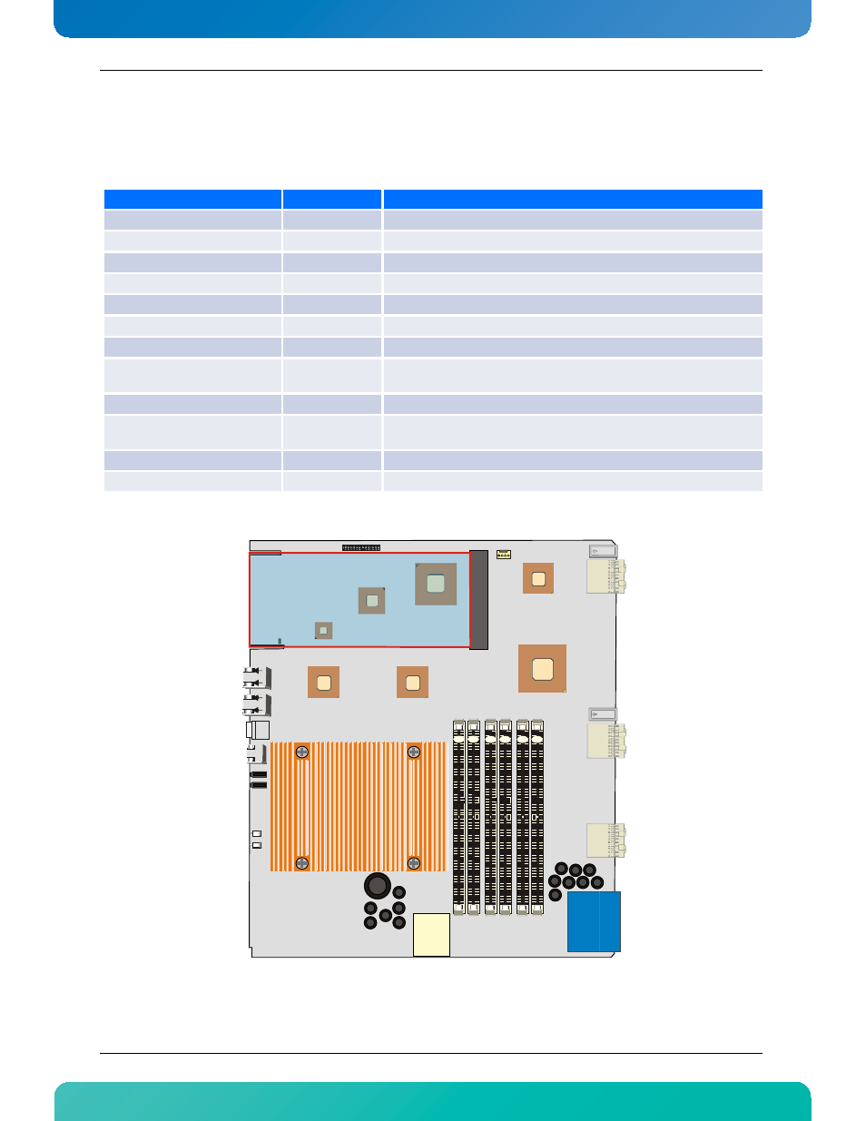
Onboard Connectors and Headers
Table 3-3:Onboard Connectors and Headers
Figure 3-2:Onboard Connectors and Headers Locations
Description
Connector
Comments
Post Codes
J2
Post Code Connector
AMC
J5
AMC Connector
Ethernet Port 1
J8
RJ-45 Ethernet Connector
Ethernet Port 0
J9
RJ-45 Ethernet Connector
USB (2x Stacked)
J10
Two stacked USB connectors
Serial Port (COM1)
J12
RJ-45 Serial Port connector
DDR3 Memory Sokcets
J13-J18
Memory Sockets
Synchronisation Clcocks, Update
Channel
J20
USB Flash Drive
J22
9 pins header for the USB Flash Drive Mezzanine
Base Interface & Fabric
Interface
J23
RTM
J30
Power & IPMB
P10
P10
J23
J30
J20
J8
J9
JP1 JP2
1 3 5 7 9 11 13
2 4 6 8 10 12 14
1 3 5 7 9 11 13
2 4 6 8 10 12 14
J10
J13
J14
J15
J16
J17
J18
J5
1
4
J2
J12
J22
Fill
first
Fill
first
Fill
first
}
Channel
2
}
Channel
1
}
Channel
0
- CP3003-SA uEFI BIOS (72 pages)
- CP3003-SA (36 pages)
- CP3002 (38 pages)
- CP3002-RC uEFI (64 pages)
- CP-RIO3-05 (42 pages)
- CP3002-RC (30 pages)
- CP342 (52 pages)
- CP930 (46 pages)
- CP932 (52 pages)
- CP346 (72 pages)
- CP384 (66 pages)
- CP383 (74 pages)
- CP382 (58 pages)
- CP381 (60 pages)
- CP372 (64 pages)
- CP371 (60 pages)
- CP-RIO3-04S (38 pages)
- CP390 (36 pages)
- CPS3410 (9 pages)
- CPS3402 (9 pages)
- CPS3105 (9 pages)
- CPS3101 (9 pages)
- CPS3003-SA (19 pages)
- PB-SIO4 (34 pages)
- PB-SIO4A (34 pages)
- PB-DOUT8 (34 pages)
- VMOD-2 (82 pages)
- VSBC-32 (110 pages)
- VM42 (62 pages)
- Bootstrap Loader (24 pages)
- VMP1 with Netbootloader (120 pages)
- VMP1 (106 pages)
- NetBootLoader (86 pages)
- VMP2 (142 pages)
- VMP3 (154 pages)
- CP-RIO6-923 (32 pages)
- CP-RIO6-923-F (32 pages)
- CP-RIO6-001 (28 pages)
- CP-RIO6-001-HD-VGA (46 pages)
- CP-RIO6-M (20 pages)
- CP-RIO6-B (28 pages)
- CP6925 (42 pages)
- CP6002 uEFI BIOS (76 pages)
- CP6002 IPMI (40 pages)
- CP6002 (42 pages)