15 leds description, 1 hot swap led (led0), 2 out of service (led1) – Kontron AT8050 User Manual
Page 43: 3 healthy led (led2), Hot swap led (led0), Out of service (led1), Healthy led (led2), Table 2-3 faceplate leds
27
www.kontron.com
2.15 LEDs Description
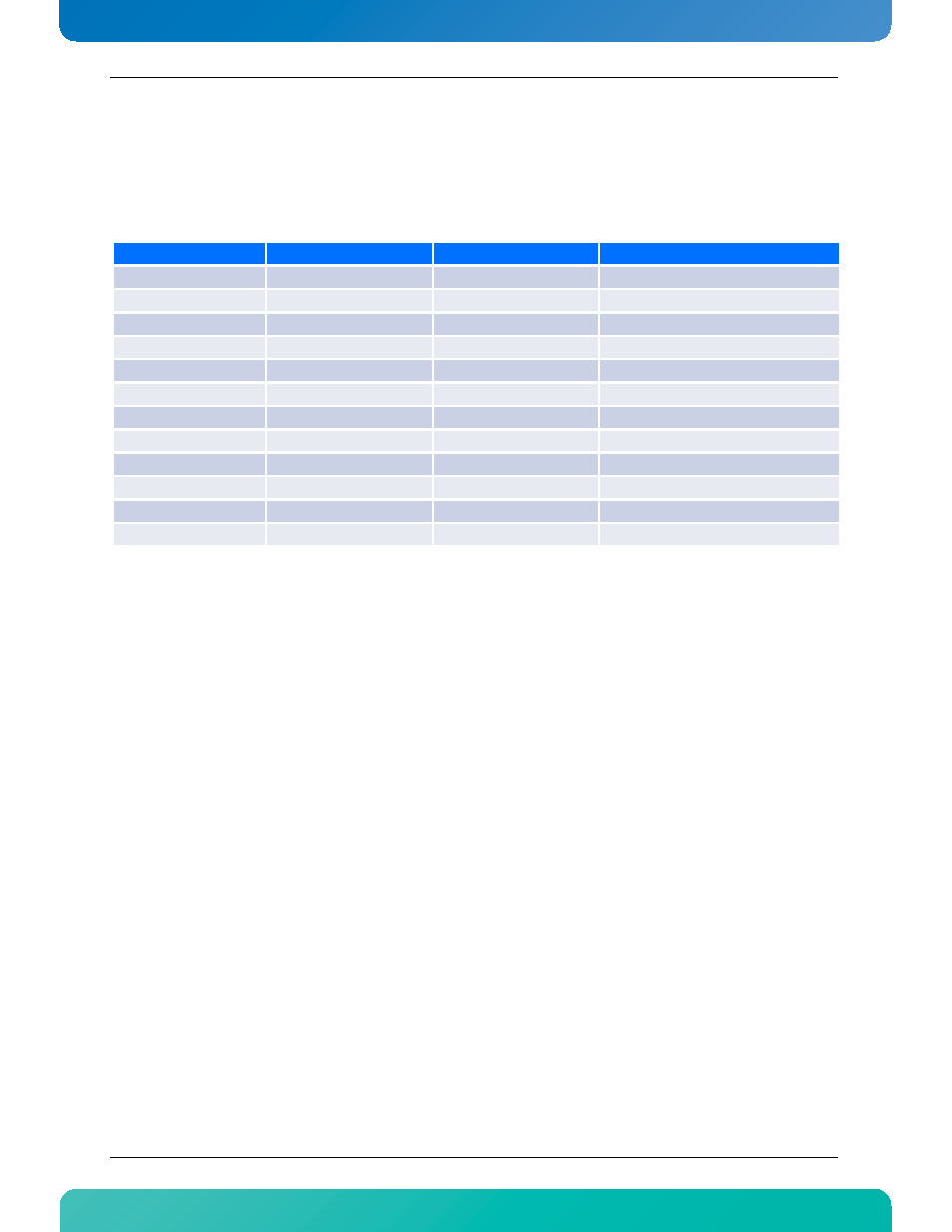
The following table lists the LED on the faceplate (not counting the RJ-45 Ethernet LED).
Table 2-3:Faceplate LEDs
2.15.1 Hot Swap LED (LED0)
The Blue / Hot Swap LED indicates the hot swap status of the RTM. The LED is ON when it is safe to remove the
RTM from the slot. During normal operation, this LED is OFF.
2.15.2 Out Of Service (LED1)
The AdvancedTCA LED1 is red or amber and indicates an Out-of-Service (OOS) condition. During normal
operation, the OOS LED is OFF. This LED is ON during firmware upgrade and is user configurable if needed by a
customer application.
2.15.3 Healthy LED (LED2)
The AdvancedTCA LED2 is green or amber and indicates a healthy condition. The healthy LED indicates if the
blade is powered up and all voltages and temperatures are within specifications. During normal operation,
this LED is ON (green). This LED is also ON (amber) when one of the RTM8050 voltage or temperature fails.
LED Name
Color
Controlled by
Description
ATCA0
Blue
IPMC
Blade Hot Swap status
ATCA1
Amber/Red
IPMC
Blade OOS (out-of-service)
ATCA2
Amber/Green
IPMC
Healthy status
ATCA3
Amber/Green
IPMC/CPU
Application specific
Strip1-L0
Amber/Green
FPGA
Base Interface Channel 1 Status
Strip1-L1
Amber/Green
FPGA
Base Interface Channel 2 Status
Strip1-L2
Amber/Green
FPGA
Fabric Interface Channel 1 Status
Strip1-L3
Amber/Green
FPGA
Fabric Interface Channel 2 Status
Strip2-L0
Amber/Green
FPGA
SAS/SATA local disks activity
Strip2-L1
Amber/Green
FPGA
SAS external disk activity
Strip2-L2
Amber/Green
FPGA
Alternate LAN configuration
Strip2-L3
Amber/Green
FPGA
Alternate LAN configuration