Assembly procedure – Elecraft PX3 Owner's Manual User Manual
Page 39
39
Assembly Procedure
Overview of the Kit
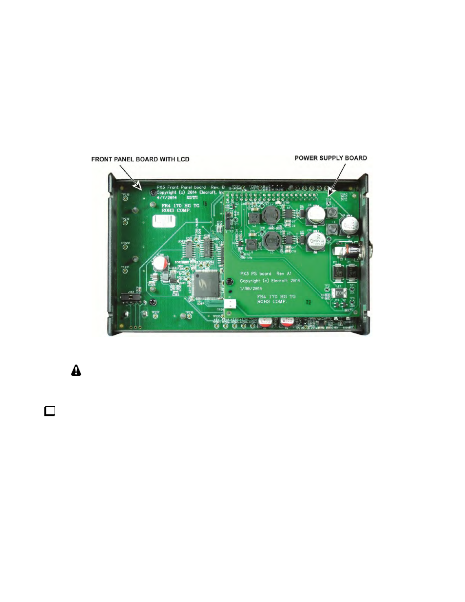
All of the circuits are contained on two pc boards, the front panel board and the power supply board. Figure
Figure 23 shows the inside of the assembled PX3 with the bottom cover removed. The front panel board with
the liquid crystal display (LCD) and switch matrix mounts in the top cover. The power supply board plugs into
the front panel board.
Figure 23 Assembled PX3 with Bottom Cover Removed.
CAUTION: The PC Boards are ESD-sensitive. Wear an ESD-safe wrist strap or touch a
metallic ground regularly while handling the boards or at any time while working inside the
PX3. See Preventing Electrostatic Discharge Damage on page 35 for more information.
Before starting construction, do a complete inventory, comparing the parts in your kit with the parts list
beginning on 36, to familiarize yourself with all of the parts and to ensure the kit is complete, but do not
remove the rubber band around front panel display board until instructed to do so in the assembly
procedure. It holds the LCD in place until the board is installed. If any parts are missing, contact Elecraft for
a replacement (see, Customer Service and Support on page 53). Recommend you also keep the printed circuit
board assemblies in their anti-static packaging until you are instructed to remove them.