Air brake, Parts list -7 – Dynojet 250i: Installation Guide User Manual
Page 73
A C C E S S O R I E S
Air Brake
Version 5
Model 200i and 250i Motorcycle Dynamometer Installation Guide
3-7
. . . . . . . . . . . . . . . . . . . . . . . . . . . . . . . . . . .
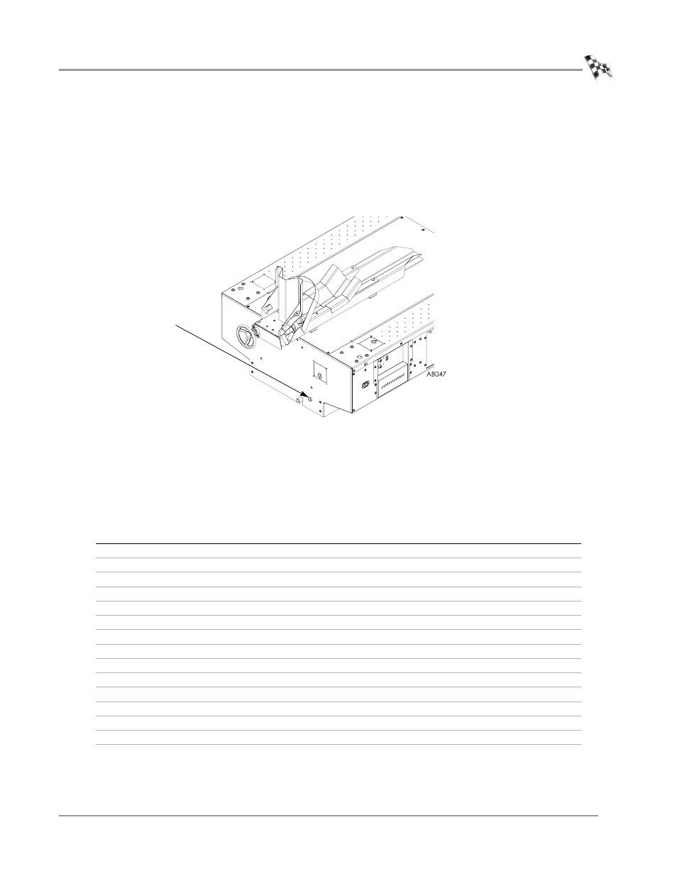
AIR BRAKE
The air brake comes installed and ready to use. You will need to provide an air hose
nipple (1/4-inch NPT) to connect your clean, dry shop air supply (60 psi, 415
kilopascal, max constant line pressure) to the dynamometer. Once air pressure is
connected and the air brake cable is routed, the air brake is ready to use.
Figure 3-6: Connect Your Shop Air Supply
P
ARTS
L
IST
The following table lists all of the parts included in the Air Brake (P/N 63920005)
Installation kit. Check your kit against the parts listed to make sure you have received
all of the parts. If any part is missing, contact Dynojet Technical Support.
part number
description
quantity
21222201
Brake Caliper Stop
1
21222601
Brake Adjusting Shim
1
21622201
Brake Bracket
1
32904080
Hairpin Cotter, 7/16-3/4” shaft size
3
32920128
Clevis Pin, 5/8 x 4”
2
36488100
Nut, 3/8-16, Nylock
1
36581270
Bolt, 3/8-16 x 3/4”, with Taper lock
2
36585670
Bolt, 3/8-16 x 3-1/2”, Hex
1
36820840
Bolt, 5/8-11 x 1, Hex
2
36952100
Washer, 5/8”, splitlock, stl
2
37620844
Woodruff Key, 1/2 x 2-3/4”, #1622-1
1
63920004
Air Brake Assembly
1
63990002
Rotor/Taper Lock Assembly with Hub and Key
1
BR102-055
Brake Spring
1
DM150-002-007
Washer, 5/16”, Flat
3
connect shop air supply