Routing cables – Dynojet 250i: Installation Guide User Manual
Page 47
I N S T A L L A T I O N
Routing Cables
Version 5
Model 200i and 250i Motorcycle Dynamometer Installation Guide
2-25
. . . . . . . . . . . . . . . . . . . . . . . . . . . . . . . . . . .
ROUTING CABLES
For the following instructions, the support arm and control panel are shown
mounted on the right side of the dyno.
R
OUTING
THE
P
ENDANT
, RS232 C
OMPUTER
C
ABLE
,
AND
C
ONTROL
P
ANEL
C
ABLE
1
Remove the two screws securing the cable pass through cover (shown in
Figure 2-25) closest to the monitor support and set it aside. The cables you will
route will be coiled inside the chassis.
2
Route the pendant cable, 9-pin RS232 computer cable (P/N 42967090), and the
15-pin control panel cable, labelled Button Panel P1, from the dyno electronics
CPU Module through the cable pass through cover on the side closest to where
you installed your monitor arm.
3
Place a split snap bushing around the pendant cable and the RS232 cable and
secure them through one hole in the cable pass through cover.
4
Place a split snap bushing around the control panel cable and secure it in the
other hole on the cable pass through cover. The bushing should be around the
cable protective wrap.
5
Secure the cable pass through cover to the dyno with the two screws removed
earlier.
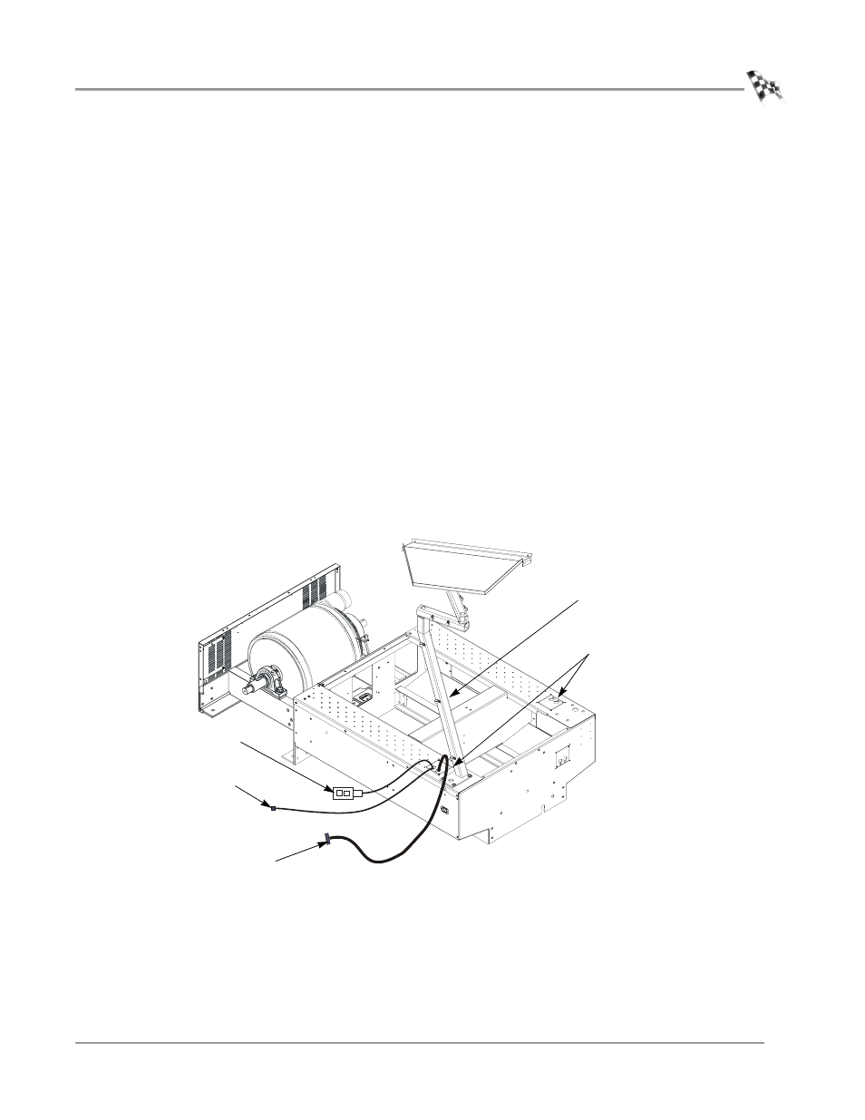
Figure 2-25: Route the Control Panel and Pendant Cables
CP026
cable pass through
cover
15-pin control panel cable
labelled Button Panel P1
pendant
monitor support
route 9-pin RS232 cable
to your computer