Dynojet 250i: Installation Guide User Manual
Page 51
I N S T A L L A T I O N
Routing Cables
Version 5
Model 200i and 250i Motorcycle Dynamometer Installation Guide
2-29
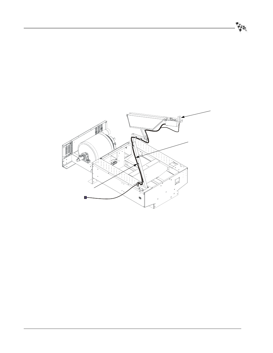
11 Place the pendant in the slot provided on the control panel and route the cable
bundle along the support arms with service loops to allow movement.
12 If you plan to route your cables through a zip tube refer to “Zip Tube” on page 2-
44 and skip the following steps.
13 Attach the cable bundle with the cable clamps that are provided using 8-32-inch
screws. Adjust the service loops to allow for easy movement of the monitor arms
without pulling on the cables.
You may want to route the RS232 connector to your computer part way up the
support arm along with the control panel and pendant cables depending on
where you your computer is located.
Figure 2-30: Secure the Control Panel Cable to the Support Arm
CP028
control panel
cable
cable clamps
pendant