Dynojet 250i: Installation Guide User Manual
Page 37
I N S T A L L A T I O N
Eddy Current Brake
Version 5
Model 200i and 250i Motorcycle Dynamometer Installation Guide
2-15
6
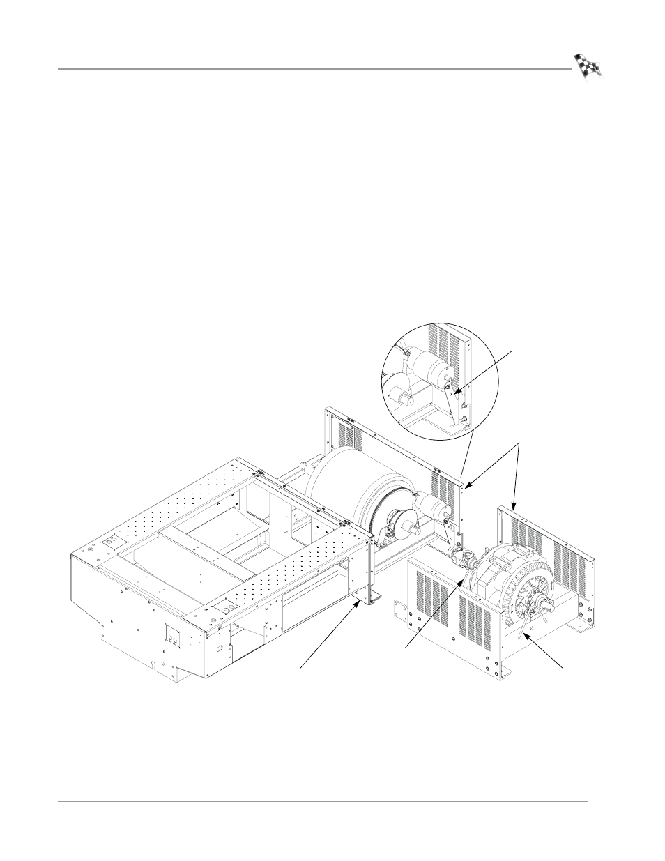
Remove the side drum cover, if not already removed, from the dyno.
Refer to Figure 2-4 on page 2-5.
7
Place the nylon loop strap through the lifting eyes on either side of the brake.
8
Using a forklift, lift the eddy current brake from the crate and place the brake near
the dyno making sure the panels on the brake and dyno are parallel.
9
Remove the eight bolts, washers, and nuts from the dyno frame where the
connector plates will attach.
10 Remove the starter brace, if present.
Note: Only remove the starter brace when installing the eddy current brake on
the left (starter) side of the dyno.
10a Remove the three bolts, washers, and nuts securing the starter brace and set
aside.
10b Remove the starter brace and set aside.
Figure 2-15: Move the Brake Next to the Dyno
EB141
lifting eye
lifting eye
line up panels
remove bolts, washers, and
nuts from dyno frame
starter brace