Memory address conflicts, Interrupt assignment conflicts – Dell OptiPlex GX1 User Manual
Page 141
Software Checks: Dell OptiPlex GX1 Small-Form-Factor System User's Guide
file:///C|/infodev/2013/eDoc/OpGX1/UG/software.htm[2/21/2013 11:47:25 AM]
Some programs may leave portions of their setup information behind, even though you have exited from
them. As a result, other programs cannot run. Rebooting your system can confirm whether or not these
programs are the cause of the problem.
Programs that use specialized subroutines called device drivers can also cause problems with your computer
system. For example, a variation in the way the data is sent to the monitor may require a special screen
driver program that expects a certain kind of video mode or monitor. In such cases, you may have to develop
an alternative method of running that particular program—the creation of a boot file made especially for that
program, for example. Call the support service for the software you are using to help you with this problem.
Memory Address Conflicts
Memory address conflicts occur when two or more devices try to access the same address in the upper
memory blocks (UMB). For example, if a network expansion card and an expanded-memory page frame are
assigned an overlapping block of addresses, a memory address conflict arises. As a result, when you try to
log in to the network, the operation fails.
To resolve this type of conflict, you can change the address of one of the devices. For example, in the case
of the network expansion card and expanded-memory page-frame address conflict, you can move the
network card to an address block in the range of CC000h through D0000h. To reassign the expansion card's
address block, refer to the documentation for the card.
Interrupt Assignment Conflicts
Problems can arise if two devices attempt to use the same interrupt request (IRQ) line. To avoid this type of
conflict, check the documentation for the default IRQ-line setting for each installed expansion card. Then
consult
to configure the card for one of the available IRQ lines.
NOTE: Table 1 lists default IRQ settings. In systems with Plug and Play capabilities, you can modify
the default settings. If you install a Plug and Play card in a Plug and Play system, the system
automatically selects an open IRQ line if any are available. If you install a non-Plug and Play or legacy
card, you may need to run the ISA Configuration Utility to determine the current IRQ settings and to
find an available IRQ line.
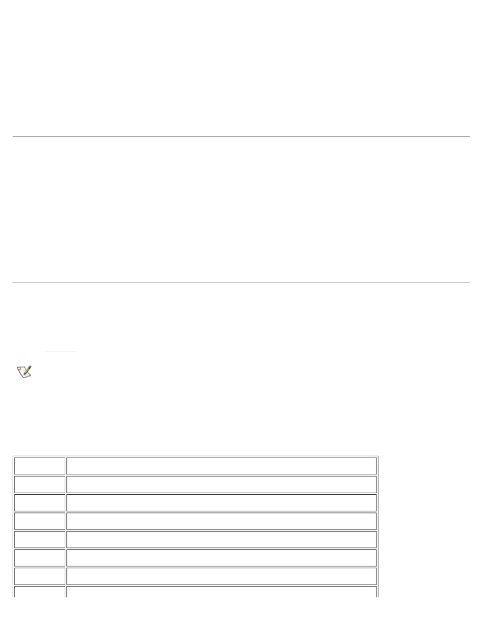
Table 1. Default IRQ Line Assignments
IRQ Line
Used/Available
IRQ0
Used by the system timer
IRQ1
Used by the keyboard to signal that the output buffer is full
IRQ2
Used by interrupt controller 1 to enable IRQ8 through IRQ15
IRQ3
Used by serial port 2
IRQ4
Used by serial port 1
IRQ5
Available