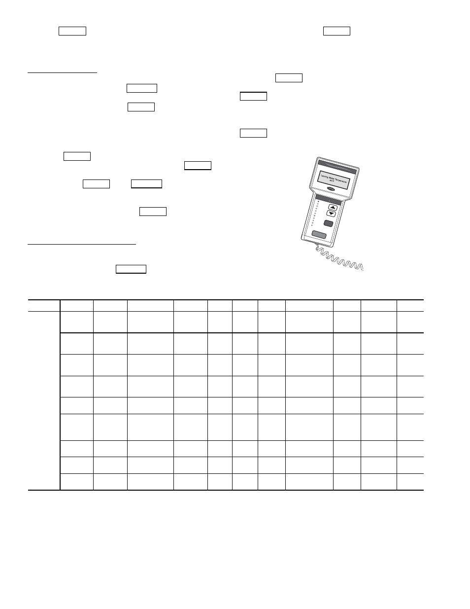
Fig. 2 — accessory navigator™ display module – Carrier AQUASNAP MPW015-045 User Manual
Page 4
4
and press
to enter the digit. Continue with the re-
maining digits of the password. The password can only be
changed through CCN operator interface software such as
ComfortWORKS, ComfortVIEW and Service Tool.
Adjusting the Contrast — The contrast of the display can be
adjusted to suit ambient conditions. To adjust the contrast of
the Navigator module, press the
key until the dis-
play reads, “Select a menu item.” Using the arrow keys move
to the Configuration mode. Press
to obtain access to
this mode. The display will read:
> TEST OFF
METR OFF
LANG ENGLISH
Pressing
will cause the “OFF” to flash. Use the up
or down arrow to change “OFF” to “ON”. Pressing
will illuminate all LEDs and display all pixels in the view
screen. Pressing
and
simultaneously
allows the user to adjust the display contrast. Use the up or
down arrows to adjust the contrast. The screen’s contrast will
change with the adjustment. Press
to accept the
change. The Navigator module will keep this setting as long as
it is plugged in to the LEN bus.
Adjusting the Backlight Brightness — The backlight of the
display can be adjusted to suit ambient conditions. The factory
default is set to the highest level. To adjust the backlight of the
Navigator module, press the
key until the display
reads, “Select a menu item.” Using the arrow keys move to the
Configuration mode. Press
to obtain access to this
mode. The display will read:
> TEST OFF
METR OFF
LANG ENGLISH
Pressing
will cause the “OFF” to flash. Use the up
or down arrow keys to change “OFF” to “ON”. Pressing
will illuminate all LEDs and display all pixels in the
view screen. Pressing the up and down arrow keys simultane-
ously allows the user to adjust the display brightness. Use the
up or down arrow keys to adjust screen brightness. Press
to accept the change. The Navigator module will
keep this setting as long as it is plugged in to the LEN bus.
Table 2 — Scrolling Marquee Display Menu Structure*
LEGEND
Ckt — Circuit
*Throughout this text, the location of items in the menu structure will be
described in the following format:
Item Expansion (Mode Name
Sub-mode Name
ITEM)
For example, using the language selection item:
Language Selection (Configuration
DISP
LANG)
ENTER
ESCAPE
ENTER
ENTER
ENTER
ENTER
ESCAPE
ENTER
ESCAPE
ENTER
ENTER
ENTER
ENTER
Run S
tatus
Service
Test
Temper
atur
es
Pressures
Setpoints
Inputs
Outputs
Configur
ation
Time Cloc
k
Oper
ating Modes
Alar
ms
ENTER
ESC
MODE
Alar
m Status
Comf
ort
Link
Fig. 2 — Accessory Navigator™ Display Module
MODE
RUN
STATUS
SERVICE
TEST
TEMPERATURES PRESSURES
SET
POINTS
INPUTS
OUTPUTS
CONFIGURATION
TIME
CLOCK
OPERATING
MODES
ALARMS
SUB-MODE
Auto
View of
Run Status
(VIEW)
Service
Test Mode
(TEST)
Unit Temperatures
(UNIT)
Pressures
Circuit A
(PRC.A)
Cooling
Setpoints
(COOL)
General
Inputs
(GEN.I)
General
Outputs
(GEN.O)
Display
Configuration
(DISP)
Time of
Day
(TIME)
Modes
(MODE)
Current
(CRNT)
Unit Run
Hour and
Start
(RUN)
Outputs
and Pumps
(OUTS)
Temperatures
Circuit A
(CIR.A)
Head
Pressure
Setpoint
(HEAD)
Circuit
Inputs
(CRCT)
Outputs
Circuit A
(CIR.A)
Unit
Configuration
(UNIT)
Month,
Date, Day,
and Year
(DATE)
Reset
Alarms
(RCRN)
Circuit and
Compressor
Run Hours
(HOUR)
Ciruit A Comp
Test
(CMPA)
Brine
Freeze
Setpoint
(FRZ)
4-20mA
Inputs
(4-20)
Unit Options 1
Hardware
(OPT1)
Daylight
Savings
Time
(DST)
Alarm
History
(HIST)
Local
Holiday
Schedules
(HOL.L)
Compressor
Starts
(STRT)
Unit Options 2
Controls
(OPT2)
Preventive
Maintenance
(PM)
CCN Network
Configuration
(CCN)
Schedule
Number
(SCH.N)
Software
Version
(VERS)
Reset Cool Temp
(RSET)
Local
Occu-
pancy
Schedule
(SCH.L)
Set Point and
Ramp Load
(SLCT)
Schedule
Override
(OVR)
Service
Configuration
(SERV)
Broadcast
Configuration
(BCST)