Carrier AQUASNAP MPW015-045 User Manual
Page 37
37
The strainers in front of the water/brine inlets of the heat
exchangers should be cleaned periodically, depending on con-
dition of the chiller water/brine.
Oil Charge
Puron refrigerant systems use a polyol ester (POE) oil. Use
only Carrier approved compressor oil. Oil should be visible in
compressor oil sight glass. An acceptable oil level is from
1
/
8
to
3
/
8
of sight glass. All compressors must be off when checking
oil level. Recommended oil level adjustment method is as
follows:
ADD OIL — Recover charge from the unit. Add oil to suction
line Schrader valve on tandem compressors sets and the com-
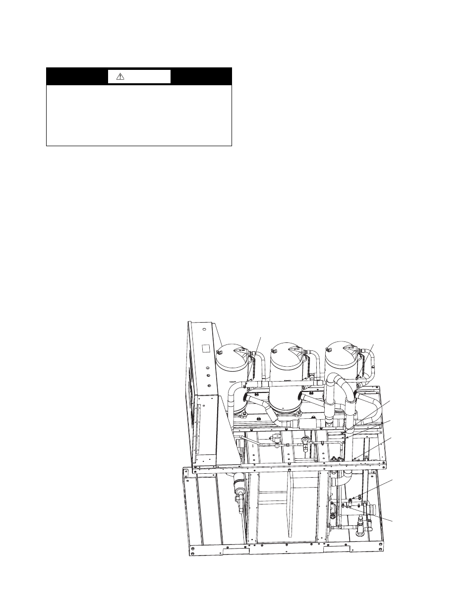
pressor Schrader on the trios. (See Fig. 21.) When oil can be
seen at the bottom of the sight glass, add oil in 5 oz increments
which is approximately
1
/
8
in oil level. Run all compressors for
20 minutes then shut off to check oil level. Repeat procedure
until acceptable oil level is present.
NOTE: Use only Carrier approved compressor oil. Approved
sources are:
Totaline . . . . . . . . . . . . . . . . . . . . . . 3MAF POE, P903-1601
Mobil. . . . . . . . . . . . . . . . . . . . . . . . . . .EAL Arctic 32-3MA
Uniqema . . . . . . . . . . . . . . . . . . . . . . . . . . . . . . RL32-3MAF
Do not reuse oil that has been drained out, or oil that has
been exposed to atmosphere.
Check Refrigerant Feed Components
FILTER DRIER — The function of the filter drier is to main-
tain a clean, dry system. The moisture indicator (described
below) indicates any need to change the filter drier. The filter
drier is a sealed-type drier. When the drier needs to be
changed, the entire filter drier must be replaced.
MOISTURE-LIQUID INDICATOR — The indicator is located
immediately ahead of the TXV to provide an indication of the
refrigerant moisture content. It also provides a sight glass for
refrigerant liquid. Clear flow of liquid refrigerant (at full unit
loading) indicates sufficient charge in the system. Bubbles in the
sight glass (at full unit loading) indicate an undercharged system
or the presence of noncondensables. Moisture in the system,
measured in parts per million (ppm), changes the color of the
indicator as follows:
Green (safe) —Moisture is below 75 ppm
Yellow-Green (caution) — 75 to 150 ppm
Yellow (wet) — above 150 ppm
The unit must be in operation at least 12 hours before the
moisture indicator gives an accurate reading, and must be in
contact with liquid refrigerant. At the first sign of moisture in
the system, change the corresponding filter drier.
THERMOSTATIC EXPANSION VALVE (TXV) — The
TXV controls the flow of liquid refrigerant to the cooler by
maintaining constant superheat of vapor leaving the cooler.
The valve(s) is activated by a temperature-sensing bulb(s)
strapped to the suction line(s).
The valve(s) is factory-set to maintain between 8° and 10° F
(4.4° and 5.6° C) of superheat leaving the cooler. Check the
superheat during operation after conditions have stabilized. If
necessary, adjust the superheat to prevent refrigerant floodback
to the compressor.
CAUTION
The compressor in a Puron
®
refigerant (R-410A) system
uses a polyol ester (POE) oil. This is extremely hygro-
scopic, meaning it absorbs water readily. POE oils can
absorb 15 times as much water as other oils designed for
HCFC and CFC refrigerants. Take all necessary precau-
tions to avoid exposure of the oil to the atmosphere. Failure
to do so could result in possible equipment damage.
HPS
DPT
RGT
SPT
EWT
(HIDDEN)
CWFS
LWT
Fig. 21 — Compressor Location — 30MP015-045 Units (30MPW045 Unit Shown)
LEGEND
CWFS
— Chilled Water Flow Switch
DPT
— Discharge Pressure Transducer
EWT
— Entering Water Thermistor
HPS
— High Pressure Switch
LWT
— Leaving Water Thermistor
RGT
— Return Gas Thermistor (Optional)
SPT
— Suction Pressure Transducer
a30-5049