Dell OptiPlex 755 User Manual
Page 80
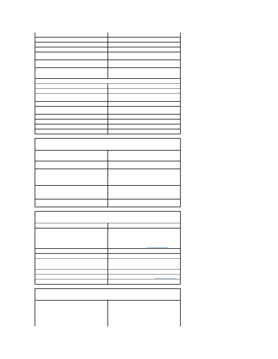
Serial
9-pin connector; 16550C-compatible
Parallel
25-pin connector (bidirectional)
Video
15-pin VGA connector
Network adapter
RJ45 connector
Optional PS/2 with secondary serial port
adapter
two 6-pin mini-DINs
USB
two front-panel and six back panel USB 2.0–compliant
connectors
Audio
two connectors for line-in/ microphone and line-out;
two front-panel connectors for headphones and
microphone
System board connectors:
SATA
three 7-pin connectors
eSATA
one 7-pin connector
Internal USB
10-pin header for optional media card reader (in 3.5-
inch drive bay)
Floppy drive
34-pin connector
Serial
12-pin connector for optional secondary PS/2 serial
port card
Fan
5-pin connector
PCI Express
one 120-pin (x16) connector
PCI 2.3
two 120-pin connectors
Front panel
40-pin connector
Key Combinations
in Microsoft® Windows® XP, brings up the Windows
Security window; in MS-DOS® mode, restarts
(reboots) the computer
starts embedded system setup (during system start-
up only)
automatically starts the computer from the network
environment specified by the remote boot
environment (PXE) rather than from one of the
devices in the system setup Boot Sequence option
(during system start-up only)
displays a boot device menu that allows the user to
enter a device for a single boot (during system start-
up only) as well as options to run hard drive and
system diagnostics
displays the Management Engine BIOS Extension Controls and Lights Power control push button Power light green light — blinking green indicates a sleep mode; amber light — blinking amber indicates a problem Power Problems .) hard drive access light green Link light solid green light indicates network connection Link integrity light (on integrated network adapter) green light for 10-Mb operation; orange light for 100- Activity light (on integrated network adapter) yellow blinking light Diagnostic lights four lights on the front panel (See Diagnostic Lights .) Standby power light AUX_PWR on the system board Power DC power supply: NOTE: Power consumption from an AC power source can be zero when the computer is unplugged from
settings screen that allows you to modify the settings
solid green indicates a power-on state.
with an installed device; solid amber indicates an
internal power problem (See
Mb operation; yellow light for 1000-Mb (1-Gb)
operation
that power source, but the internal battery does
draw a minute amount of power from the power
supply even when the computer is not drawing
power from the AC power source.