25 series row-unit side wheels, Caution – Great Plains YP1625 Operator Manual User Manual
Page 64
1625
401-182M
7/12/2005
62
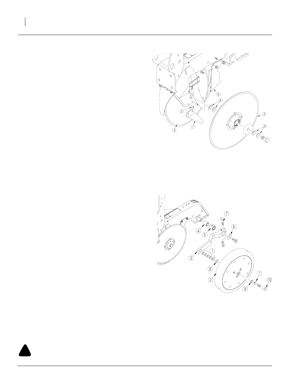
25 Series Disk Spreaders and Scrapers
NOTE: It is normal for the blade spreader to have some
looseness in the holder and between the blades. Some
looseness is required for proper operation.
Refer to Figure 69
1.
Remove side gauge wheels from arms to access row-
unit disks and scrapers.
2.
With the unit raised, check the blade spreader (1) for
wear. Replace spreader if it is 1/2 inches wide or nar-
rower. To replace, remove disk blade (3). Drive out the
roll pins (2) and install a new spreader.
3.
When reinstalling disk blades, put two shims (4) be-
tween bearing and shank on each blade. Tighten bolts.
NOTE: You may need fewer washers on worn disks.
4.
Check that outside disk scrapers (5) are formed to disk
blades to help remove any mud. Bend and twist scrap-
ers to fit blades as necessary. After every 200 acres of
operation, check outside scrapers for proper adjust-
ment and wear. Replace outside scrapers as neces-
sary.
25 Series Row-Unit Side Wheels
Refer to Figure 70
1.
Lift row-unit side wheel off the ground. Move tire in and
out to check for end play. Check for roughness in bear-
ing by rotating wheel. If the bearings are rough, inspect
and replace if necessary.
2.
Check for the correct number of machine washers (1)
and flat washer (8) between the side gauge wheel (2)
and the wheel arm (3). There must be five machine
washers (1) and one flat washer (8) between the wheel
bearing and arm with the machine washer (8) next to
the arm. There should be one machine washer (1) and
one lock washer (9) on the outside of the wheel. When
installed, the wheel should turn freely and not hit the
arm at the curve. Do not add any more washers than
necessary.
3.
Disassemble side gauge wheel arm (3) from unit. Re-
move bushing (4) from sleeve (5) and check bushing for
wear. Replace bushing if necessary.
4.
When reinstalling side gauge wheels, align tab on hex
adjustment (6) with notch in bushing. Replace bolt and
tighten.
5.
To prevent plugging loosen clamp bolt (7) and slide arm
inward to take up gap between side wheel and disk
blade.
6.
Adjust side gauge wheels. Refer to “Adjustments,” page
31.
!
CAUTION
Disk edges are sharp. Be careful when working in this area.
21893
21894
Figure 69
Spreaders and Scrapers
Figure 70
Side Wheels