Side gauge wheels – Great Plains YP1625 Operator Manual User Manual
Page 38
1625
401-182M
7/12/2005
36
Side Gauge Wheels for 25 Series Row-Units
Refer to Figure 31
The side gauge wheels have two, interrelated
adjustments:
• angle of side gauge wheel, and
• distance between side gauge wheel and row
unit disk.
Refer to Figure 32
Adjust side-gauge-wheel angle so the wheels
contact the row unit disks between 4 and 8 o’clock
at the bottom of wheel.
At the same time, keep the side gauge wheels
close to the row-unit disks so row-units do not
plug with soil or trash but far enough out so the
disks and wheels turn freely.
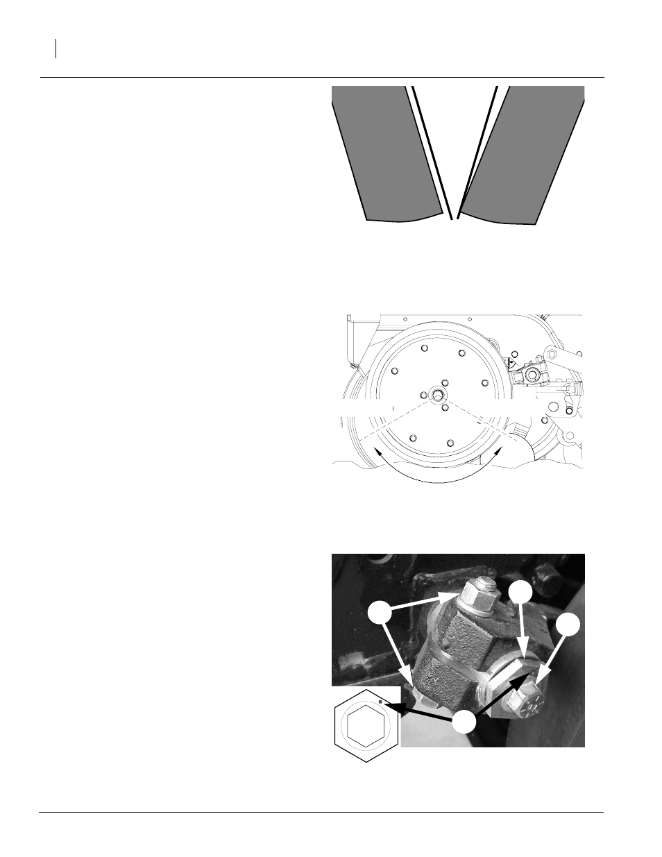
Refer to Figure 33
To adjust side gauge wheels:
1.
Raise planter slightly to remove weight from
side gauge wheels.
2.
Loosen hex-head bolt (1). Move wheel and
arm out on o-ring bushing.
3.
Loosen pivot bolt (2). Turn hex adjuster (3) so
roll pin (4) is at 1 o’clock. Use this as the start-
ing point for adjustment.
4.
Move wheel arm in so side gauge wheel con-
tacts row unit disk. Tighten hex-head bolt (1)
to clamp arm around bushing and shank.
5.
Check the wheel-to-disk contact. Lift wheel
and arm. When let go, the wheel should fall
freely.
• If wheel does not contact disk from 4 to 8
o’clock, move hex adjuster until wheel is an-
gled for proper contact with disk.
• If wheel does not fall freely, loosen hex-
head bolt (1) and slide wheel arm out just until
wheel and arm move freely. Retighten hex-
head bolt.
6.
Keep turning hex adjuster and moving wheel
arm until the wheel is adjusted properly.
When satisfied, tighten pivot bolt to 110 foot-
pounds. Tighten pivot bolt (2).
Side Gauge
Wheel
Side Gauge
Wheel
Row-Unit
Disks
Incorrect
Correct
Figure 31
Side Gauge Wheels
17812
Figure 32
Wheel-to-Disk Contact Area
8 o’clock
4 o’clock
Figure 33
Side Gauge Wheel Adjustment
Starting Point
18450
2
1
3
4
Note: Wheel touches at bottom and gaps open 3/8” to
5/8” at top.