Disk adjustment marker width, Caution – Great Plains YP1625 Operator Manual User Manual
Page 49
7/12/2005
401-182M
47
Adjustments
Disk Adjustment
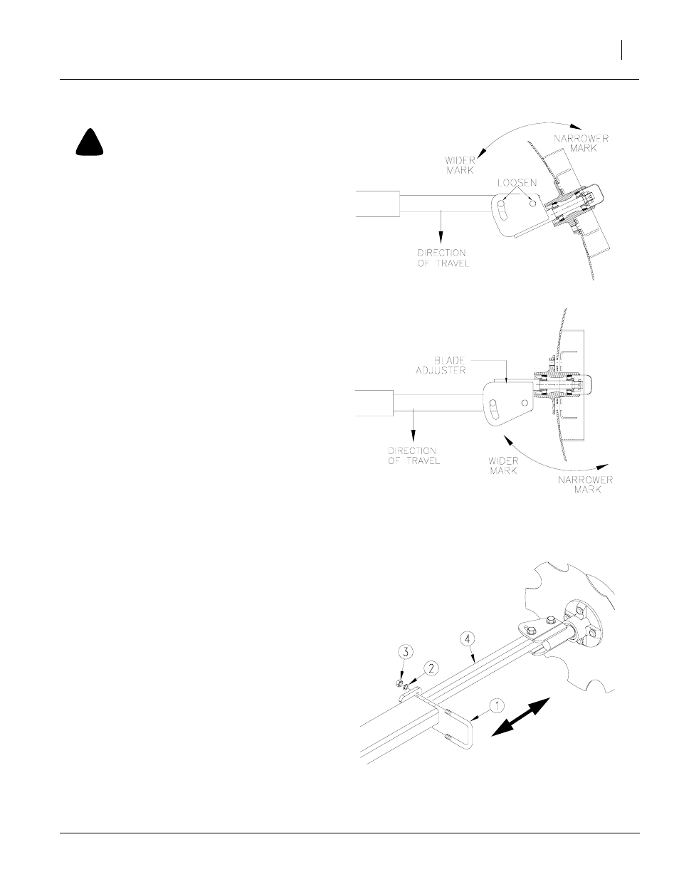
!
CAUTION
Marker disks may be sharp. Use caution when making
adjustments in this area.
Refer to Figure 57
There are two ways you can change the mark left
by the marker disk.
1.
Disk Angle. To change angle of cut, loosen
1/2-inch bolts holding disk assembly. Rotate
disk assembly as desired.
2.
Direction of Cut. To change direction of cut
and throw dirt either in or out:
a.
Reverse blade and depth band by re-
mounting lug bolts on disk hub.
b.
Reverse angle of assembly by removing
two 1/2-inch bolts holding disk assembly.
Turn disk assembly one-half turn. Rein-
stall 1/2-inch bolts and set disk angle.
Marker Width
Refer to Figure 58
To adjust marker width, loosen nuts (3) on
U-bolts (1). Move marker disk tube (4) in or out to
get the proper adjustment. Measure from the end
of disk tube (4) to the end of the second section.
This distance should be 10 1/2” for 15” row spac-
ing and 25 1/2” for 20”, 30” and twin-row spacing.
Use the steps below to double check for your row
spacing.
To measure for marker width adjustment:
1.
Lower planter in the field and drive forward a
few feet.
2.
Measure from the middle of the outside row to
the mark in the ground made by marker disk.
3.
Adjust as needed.
Figure 57
Marker Disk Blade Adjustment
11757
11248
Disk Angle
Direction of Cut
Figure 58
Marker Width Adjustment
18878