Leveling frame side-to-side, 1” to 1 1/4” starting position – Great Plains YP1625 Operator Manual User Manual
Page 19
7/12/2005
401-182M
17
Preparation and Setup
Leveling Frame Side-to-Side
All frame sections must be level to maintain even
seeding depth. Before using the planter in the field,
follow these steps to make sure the planter is level
side-to-side.
Periodic frame-leveling adjustments should not be
necessary, but if you are having problems with un-
even depth, check planter levelness and follow these
procedures.
Before making any adjustments be sure the lift cylin-
ders are rephased and operating properly.
Complete the steps under “Bleeding Hydraulics,”
page 15, before proceeding.
Refer to Figure 4
1.
Lower the planter fully to field position.
2.
Set the 3-point for 40”. When setting hitch at 40”,
lower lift cylinders completely, then adjust.
Important: Planter must be fully lowered to field
position and hitch height must be set before mak-
ing side-to-side adjustments.
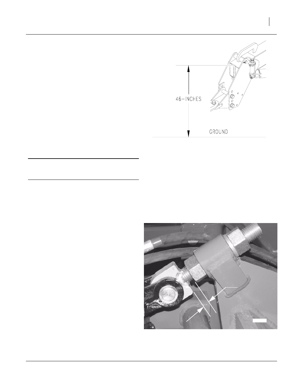
Refer to Figure 5
3.
Locate the threaded eye bolt at the base end of
the gauge-wheel cylinders. The eye bolt is locked
in place by a jam nut. Observe the amount of
thread exposed between the eye and lower nut.
This should measure 1” to 1 1/4”, if so, no initial
adjustment is needed. Go to step 4.
4.
If the exposed threads between the eye and low-
er nut does not measure 1 1/4”, loosen and ad-
just the jam nuts until it does. Repeat for other
end of planter.
5.
Move the planter to a level area. With the planter
unfolded, raise the planter to its highest position
with the lift cylinders. With the tractor idling,
rephase the cylinders by holding the hydraulic le-
ver on for an additional 30 seconds. Immediately
lower the planter until the row-units are just ready
to touch the ground.
6.
Move the gauge-wheel eye bolts until the row-
units on the outside end of the planter are the
same height as the center row-units.
NOTE: Eye-bolt adjustments are easier if the planter
is first lowered to the ground to remove some of the
force on the cylinders.
7.
Repeat the steps above until the planter is level
side-to-side when planting in actual seeding con-
ditions.
21926
21930
1” to 1 1/4”
Starting
Position
Figure 5
Frame Leveling
Figure 4
Base Height