08 recommended cutting speeds, Recommended cutting speeds -14, Pak 200i – Tweco PAK 200i User Manual
Page 52: Swirl effect on side characteristics of cut
PAK 200i
4-14
OPERATION
Manual 0-5335
Dross Build-up and Top Spatter
Dross is molten material which is not blown out of the cut area and re-solidifies on the plate. Top spatter is
dross which accumulates on the top surface of the workpiece. Excessive dross may require secondary clean-up
operations after cutting.
Kerf Width
The width of material removed during the cut.
Nitride Build-up
Nitride deposits which may remain on the cut edge of the carbon steel when nitrogen is present in the plasma
gas stream. Nitride buildups may create difficulties if the steel is welded after the cutting process.
Direction of Cut
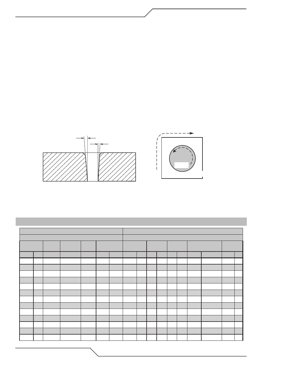
The plasma gas stream swirls as it leaves the torch to maintain a smooth column of gas. This swirl effect results
in one side of a cut being more square than the other. Viewed along the direction of travel, the right side of the
cut is more square than the left.
Right Side
Cut Angle
Left Side
Cut Angle
A-00512
Scrap
Clockwise
Counter-
Clockwise
Art # A-04182
Workpiece
Scrap
Swirl Effect on Side Characteristics Of Cut
To make a square - edged cut along an inside diameter of a circle, the torch should move counterclockwise around
the circle. To keep the square edge along an outside diameter cut, the torch should travel in a clockwise direction.
4.08 Recommended Cutting Speeds
Type Torch: PCH-200
Type Material: Aluminum
Type Plasma Gas: Air
Type Secondary Gas: Air
Thickness
Tip
Output
Amperage
Speed
(Per Minute)
Standoff
Plasma Gas
Press
Sec Gas
Press
Total Flow (SCFH) Pierce Height
Inches mm (Cat. No.) Volts (VDC) (Amps) Inches Meters Inches mm
psi
bar psi bar Plasma Secondary Inches mm
0.032 0.8 32-1320
100
35
400
10.2
0.13
3.2
63
4.3
60
4.1
50
340
0.13 3.2
0.050 1.3 32-1320
100
35
250
6.4
0.13
3.2
63
4.3
60
4.1
50
340
0.13 3.2
0.063 1.6 32-1320
100
35
125
3.2
0.13
3.2
63
4.3
60
4.1
50
340
0.13 3.3
0.091 2.3 32-1320
110
35
90
2.3
0.13
3.2
63
4.3
60
4.1
50
340
0.13 3.3
0.125 3.2 32-1320
115
35
60
1.5
0.13
3.3
63
4.3
60
4.1
50
340
0.13 3.3
0.063 1.6 32-1321
118
70
200
5.1
0.13
3.3
50
3.4
60
4.1
60
332
0.13 3.3
0.125 3.2 32-1321
125
70
125
3.2
0.13
3.3
70
4.8
60
4.1
82
332
0.13 3.3
0.188 4.8 32-1321
125
70
85
2.2
0.13
3.3
70
4.8
60
4.1
82
332
0.13 3.3
0.25
6.4 32-1321
130
70
65
1.7
0.13
3.3
70
4.8
60
4.1
82
332
0.13 3.3
0.375 9.5 32-1321
140
70
25
0.6
0.13
3.3
70
4.8
60
4.1
82
332
0.25 6.4
0.500 12.7 32-1321
145
70
15
0.4
0.13
3.3
70
4.8
60
4.1
82
332
0.25 6.4
0.25
6.4 32-1322
125
120
125
3.2
0.19
4.7
60
4.1
60
4.1
78
340
0.25 6.4
0.375 9.5 32-1322
130
120
70
1.8
0.19
4.8
60
4.1
60
4.1
78
340
0.25 6.4