Warning, Nforce™ led lightbar, Fixed height brackets and hook mounting – SoundOff Signal nFORCE LED User Manual
Page 4
IMPORTANT INFORMATION:
Warning devices are strictly regulated and governed by Federal, State and Municipal ordinances. These devices shall be used ONLY on approved vehicles. It is the sole responsibility of the user of these devices to ensure compliance.
To review our Limited Warranty Statement & Return Policy for this or any SoundOff Signal product, visit our website at
www.soundoffsignal.com/sales-support.
If you have questions regarding this product, contact
Technical Services, Monday - Friday, 8 a.m. to 5 p.m. at 1.800338.7337 (press #4 to skip the automated message).
Questions or comments that do not require immediate attention may be emailed to
SUPERIOR CUSTOMER RELATIONSHIPS. SMARTLY DESIGNED LIGHTING & ELECTRONIC SOLUTIONS.
nFORCE™ LED Lightbar
nForce Lightbar 05.14
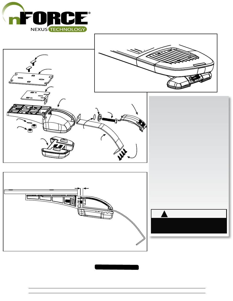
1. Keeping the lightbar level with the road, attach Mount-
ing Feet to the roof of the vehicle using the 2 supplied
T-Slot bolts. If the lightbar needs to be leveled, a 1.5°
wedge has been provided.
2. Place lightbar centered on the roof, and hold brackets
up to the lightbar. A 1/4" to 1/2" gap should be between
the hook bracket and front wall of the mounting foot prior
to putting any tension on the hook bracket bolt (See Fig-
ure 3). Adjust the mounting foot position to accomodate
for this gap.
3. Tighten hook bracket bolts with max torque 10in-lbs.
DO NOT OVERTIGHTEN! Bar is secure once split
lock washer has been compressed. Using holes in the
hook bracket as a template, drill 4 holes in the roof us-
ing the appropriate size drill. Secure hook bracket to roof
with 4 screws on each side.
4. Install the cover door over the hook bracket bolt to fin-
ish the assembly. Place tab of one side into place and
then push the second tab into place with a flat-head
screw driver.
FIXED HEIGHT BRACKETS AND
HOOK MOUNTING
!
WARNING
Route wires only in locations that are not subjected to
potential wear. Make sure to avoid routing wires in the
deployment area of your air bag. Refer to your vehicle’s
owner’s manual for airbag deployment zone.
1/4" - 1/2" Gap Required
Figure 1.
Figure 2.
Figure 3.
T-Slot Attachment x2
(1st slid into extrusion)
1.5° Wedge
Metal Nut Bracket
Mounting Foot
Hook Bracket
Hook Bracket Bolt
Hook Bracket
Cover Door
Flat Washer
Lock Nut
Rubber Pad
Flat Washer
Split Ring Lock Washer
4.
#8-1/2" Truss Head
Sheetmetal screw