SoundOff Signal nFORCE Oval Recess Mount User Manual
SoundOff Signal Lighting
ENFSRV(xx) 10.14
INSTALLATION:
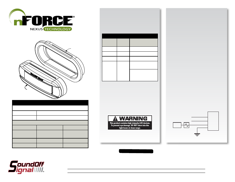
1) Establish a position on the vehicle. Use the
cutout template (provided) on 2nd page and cut
hole. Insert grommet into cutout first and then
press the light assemble into the grommet.
nFORCE 6” Oval Recess Mount Light, SAE Class 1
ENFSLSRV(x)(yyy) - Custom Ordered Through Configurator
ENFSRV1(x) - 6 LED
ENFSRV2(x) - 9 LED
ENFSRV3(x) - 12 LED
TECHNICAL SPECIFICATIONS
6” OVAL RECESS MOUNT nFORCE
Dimensions:
7.75”L x 3.25”H x 1.65”D
Input Voltage:
10 - 16 Vdc or 10 - 30 Vdc *
CURRENT CONSUMPTION PER MODULE
10-16 Vdc
10-30 Vdc *
6, 12 Split &
18 Tri-Color
<1.0A @12.8 Vdc
<0.6A @25.6 Vdc
9 LED Single Color <1.5A @ 12.8 Vdc
<0.9A @ 25.6 Vdc
12 LED Single Color
<2.0A @12.8 Vdc
<1.2A @ 25.6 Vdc
* - Special Order
nFORCE SECONDARY INFORMATION:
IMPORTANT INFORMATION:
Warning devices are strictly regulated and governed by Federal, State and Municipal ordinances. These devices shall be used ONLY on approved vehicles. It is the sole responsibility of the user of these devices to ensure compliance.
To review our Limited Warranty Statement & Return Policy for this or any SoundOff Signal product, visit our website at
www.soundoffsignal.com/sales-support.
If you have questions regarding this product, contact
Technical Services, Monday - Friday, 8 a.m. to 5 p.m. Eastern Time or during extended after hours coverage between 5 p.m. & 8 p.m. Eastern
Time at
1.800338.7337 (press #4 to skip the automated message).
Questions or comments that do not require immediate attention may be emailed to
SUPERIOR CUSTOMER RELATIONSHIPS. SMARTLY DESIGNED LIGHTING & ELECTRONIC SOLUTIONS.
1.
WIRE HOOK-UP TABLE
WIRE
COLOR:
LIGHT
HEAD
FUNCTION:
RED
1
Power
BLACK
1
Ground
**GREEN
1
Sync2 *
WHITE
1
To Ground: Pattern
Select/ Setup
To Power: Secondary
Fuction
-see page 2-
** To sync multiple nFORCE lights,
connect the Green wires from each light
together. *Individual light applications connect
the Green & Blue wires together.
* Will NOT work w/ other sync products such as
Ghost, LED3, & Intercector.
PATTERN SELECT & SYNC
CONFIGURATION INSTRUCTIONS
Connecting the WHITE or Yellow (Dual) wire to
power will allow you to use the secondary function
on your Nexus Secondary Light.
SECONDARY FUNCTION:
• 1-color module = Cruise Mode (10% brightness,
non-flashing)
• 2 - color modules = Separate Color Control (see
Setup Table) or Takedown (100% steady-burn of
the 2nd color)
• 3 - color modules = Takedown (100% steady-
burn of the 3rd color)
SETUP LIGHTS:
Simultaneous or Alternate Function
•1 or 2. The modules will flash simultaneously if
they are set to the same number. The modules will
have an alternate flash if set to different numbers.
Color swap
• Off or On. 2-color and 3-color modules, it changes
which color flashes first.
Separate color control(2 color lights only)
•Allows manual switching of flashing color. When
this feature is programmed in the On state: the
light will jump to the first pattern of the 1-color
patterns, you will only be able to choose 1-color
patterns, and Color Swap will be programmed to
Off. To select a 2-color pattern, program this
feature to the Off state.
*To turn off
Seperate Color Control you must do a
factory reset.
BLACK
RED
WHITE
GREEN
+Vdc
A FUSE
5
Sync
Pattern/Function
GASKET
LIGHT ASSEMBLY