SoundOff Signal Predator 2 Surface Mount Light User Manual
Single surface mount warning system, Warning, Assembly instructions ep2ssmdb(x)
EP2SSMDBx 2.09
SINGLE SURFACE MOUNT
WARNING SYSTEM
ASSEMBLY INSTRUCTIONS
EP2SSMDB(x)
PATTERN SELECTION
1. Disconnect WHITE wire from any connections if applicable.
2. Turn PREDATOR II ON.
3. Momentarily touching and removing the WHITE wire(s) to ground
will advance the PREDATOR II to the next flash pattern. Touching and
removing the White wire for more than a few seconds will allow you to change the
PREDATOR II to the previous pattern. See flash pattern table. Continuing to touch
and remove the WHITE wire(s) to ground will allow you to scroll through the pattern
list. After pattern #33 is reached the list will start over again at pattern #1.
NOTE: The PREDATOR II is equipped with flash pattern memory. Once you have
selected a pattern the PREDATOR II will always activate to that pattern every time
the unit is turned on. Tape up and secure WHITE wire so that it will not accidentally
change your selected pattern.
PATTERN RESET
1. Remove Power.
2. Place WHITE (sync) wire to ground.
3. With sync wire grounded, re-power RED wire.
4. Maintain for one second (light will dim).
5. Remove power and ground (pattern 1 set).
SLAVE MODE
The PREDATOR II is capable of being activated through the use of a user supplied
flasher by putting it in slave mode.
1. Permanently connect the PREDATOR II WHITE and BLACK wire to a good,
convenient ground.
2. Connect the PREDATOR II RED wire, through a 5Amp fuse, to the output of a
+10-30Vdc switching flasher.
NOTE: The PREDATOR II is a factory sealed unit that CANNOT be serviced in the
field. Any attempt to gain access to the PREDATOR II unit will most likely cause
permanent damage and void its warranty.
MOUNTING INSTRUCTIONS
Important: DO NOT over tighten mounting
screws or nuts. This could cause permanent
damage to the bracket. Use appropriate
hardware for mounting.
1. Locate flat mounting location for PREDATOR II
Surface Mount LEDs.
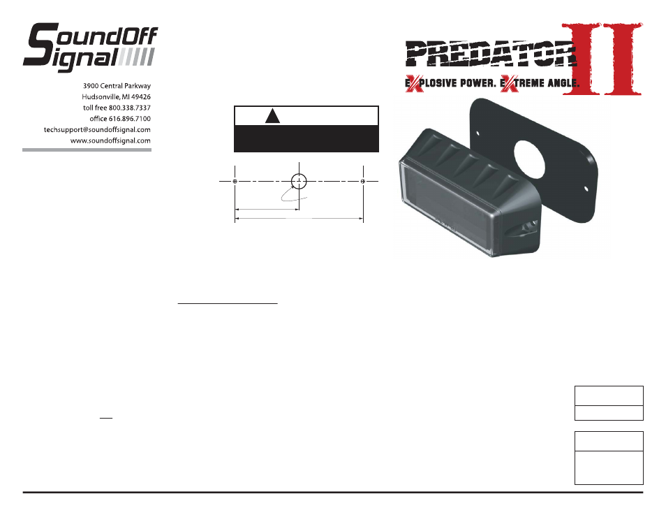
2. Using the gasket as a template, mark and drill
pilot holes for mounting screws.
Note: The mounting holes will be
slightly greater than 4-1/8" center to center.
These dimensions are for approximate
reference only.
3. Drill 1/2" hole at the center of the mounting
hole pattern (see layout - do not scale).
Note: If possible, the back side of this
hole should be deburred where drill
breakthrough occurs.
4. Route cable through hole in gasket and make
electrical connections (Red-power,
Black-ground. White is for ID and pattern
selection and will be taped after selection is
made). If the final location of the cable will be
inaccessible, ID and pattern selection must be
made before final installation.
5. Install gasket over rear of light and loosely
install unit with #8 self-threading screws and
plastic washers. Washer must be installed
under the head of the screw. Note: Gasket
must be used to prevent oxidation and
galvanization of the mounting surface if
differing metals come in contact.
6. When final position of unit is obtained tighten
screws. DO NOT OVER-TIGHTEN!
IMPORTANT: DO NOT connect this
device to a strobe power supply.
OPERATING INSTRUCTIONS
See setup procedure on second page.
The single Predator II comes equipped with an
internal flasher with 33 user selectable patterns
that can be synchronized either alternating or
simultaneous with up to three other lights. It
can also be put into slave mode and driven
through an external flasher.
1. Connect the PREDATOR II BLACK wire to a
good, convenient ground.
2. Connect the PREDATOR II RED wire to one
side of a user supplied on/off switch. Connect
the other side of the switch, through a 5Amp
fuse, to a source of +10-30Vdc.
WIRE HOOK-UP TABLE
(TOP LED MODULE)
Wire Color Connect to:
Red
+10-30Vdc
Black Ground
(-)
White ID/Pattern
Select
CURRENT DRAW AT
12.8Vdc
1.1 Amps (All configs.)
!
WARNING
This product contains high intensity LED
devices. To prevent eye damage, DO NOT
stare into light beam at close range.
WARNING
: Warning devices are strictly
regulated and governed by Federal, State
and Municipal ordinances. These devices
shall be used ONLY on approved vehicles.
It is the sole responsibility of the user of
these devices to ensure compliance.
DRILL 1/2" DIA.
HOLE ON CENTER
4-1/8”
2-1/16”