SoundOff Signal Predator 2 DDG (Dual) User Manual
Dual exterior deck / grille warning system, Warning, Assembly instructions ep2dgs1(x)
EP2DGS1(x) 02/08
WARNING
: Warning devices are strictly
regulated and governed by Federal, State and
Municipal ordinances. These devices shall be
used ONLY on approved vehicles. It is the sole
responsibility of the user of these devices to
ensure compliance.
DUAL EXTERIOR DECK / GRILLE
WARNING SYSTEM
ASSEMBLY INSTRUCTIONS
EP2DGS1(x)
IMPORTANT: DO NOT connect this
device to a strobe power supply.
!
WARNING
This product contains high intensity LED
devices. To prevent eye damage, DO NOT
stare into light beam at close range.
OPERATING INSTRUCTIONS
See setup procedure on second page.
The single Predator II comes equipped with an
internal flasher with 33 user selectable patterns
that can be synchronized either alternating or
simultaneous with up to three other lights. It
can also be put into slave mode and driven
through an external flasher.
1. Connect the PREDATOR II BLACK wire to a
good, convenient ground.
2. Connect the PREDATOR II RED wire to one
side of a user supplied on/off switch. Connect
the other side of the switch, through a 5Amp
fuse, to a source of +10-30Vdc.
BRACKET MOUNTING
Important: DO NOT over tighten mounting
screws or nuts. This could cause
permanent damage to the bracket
1. Locate flat mounting location for Predator
II Light Bracket.
2. When position of bracket is determined
use supplied template for hole locations.
3. Drive in Customer Supplied Hex Head
screws. Leave about a 1/16” space
between the mounting surface and
underside of screw head.
4. Place Light over screws using the holes in
brackets and slide to the right to lock the
brackets underneath the head of the
bolts.
5. Using a open-end wrench, tighten the hex
head bolts down tight to secure the light
to the mounting surface.
6. Adjust angle of the light to best suit your
application by loosening the 2 nuts on
either end of the light.
7. After the Predator is set to the desired
angle, tighten the 2 nuts on either end of
the light. DO NOT OVER TIGHTEN nuts
as damage to bracket or light can occur.
Tighten nut until snug plus 1/8 turn.
8. Make electrical connections using the
following instructions.
Install Screws (user supplied)
first using template below
Plac
e Light o
v
er scr
ews using k
e
y
w
a
y
in br
ack
e
ts
Slide Light to the Right and tighten screws using box end wrench
7.07”
SCREW PLACEMENT DRILL TEMPLATE
(Be sure to use appropriate drill size for your screw size)
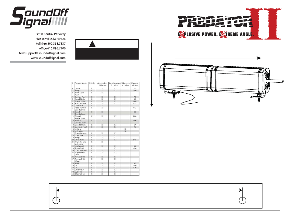
FLASH PATTERNS for
DUAL HEAD EXTERIOR PREDATOR II (EP2DGS1(x))
ID SELECTION
1. Identify which pattern and sequence preferred
and look up ID#s on the table provided on the
second page.
2. Connect the PREDATOR II WHITE wire to the
same source as the RED wire (Note: you will
need to disconnect after power is applied)
3. Turn PREDATOR II ON
4. Without disconnecting power from unit,
disconnect WHITE wire
5. Momentarily Touching and removing the WHITE
wire to ground will advance the PREDATOR II
to the next ID#. The ID# can be identified by
the number of sequential flashes from 1 up to 4.
ID# 1 should be used if not synchronizing with
other lights.
6. Once the ID is selected DISCONNECT power.