Nforce™ led lightbar – SoundOff Signal nFORCE LED User Manual
Page 10
IMPORTANT INFORMATION:
Warning devices are strictly regulated and governed by Federal, State and Municipal ordinances. These devices shall be used ONLY on approved vehicles. It is the sole responsibility of the user of these devices to ensure compliance.
To review our Limited Warranty Statement & Return Policy for this or any SoundOff Signal product, visit our website at
www.soundoffsignal.com/sales-support.
If you have questions regarding this product, contact
Technical Services, Monday - Friday, 8 a.m. to 5 p.m. at 1.800338.7337 (press #4 to skip the automated message).
Questions or comments that do not require immediate attention may be emailed to
SUPERIOR CUSTOMER RELATIONSHIPS. SMARTLY DESIGNED LIGHTING & ELECTRONIC SOLUTIONS.
nFORCE™ LED Lightbar
nForce Lightbar 05.14
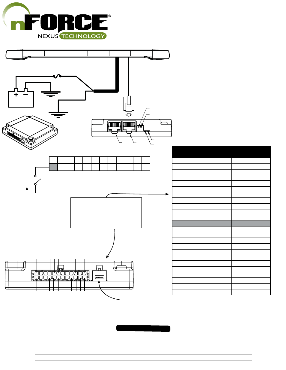
Wire Pin #
Wire Color
Wire Function
1
Blue/White
Rear Corners
2
Green/White
Rear Inboard 1
3
Gray
Mode Select
4
Black
Cruise Mode
5
Light Green
Scene Lighting
6
Brown/White
Takedown Flash
7
Purple
Low Power
8
White
Pattern Select / Tail
9
Black/White
Left Turn
10
Gray/White
Arrow - Right
11
Purple/White
Arrow – Left
12
Pink/White
Ignition Input
13
Blue
Front Corners
14
Green
Front Inboard 1
15
Yellow
Front Inboard 2
16
Orange
Front Inboard 3
17
Red
Alley Passenger
18
Pink
Alley Driver
19
Red/White
Alley Flash
20
Brown
Takedown
21
Yellow/White
Rear Inboard 2
22
Orange/White
Rear Inboard 3
23
Red/Black
Right Turn
24
Light Green/White
Sync
24 23 22 21 20 19 18 17 16 15 14 13
12 11 10
9
8
7
6
5
4
3
2
1
Connector Pinning Chart
PIN#24 - Light Green/ White PIN#23 - R
ed Black
PIN#22 - Orange/ White
PIN#21 - Y
ellow/ White
PIN#20 - Brown PIN#19 - R
ed/ White
PIN#18 - P
ink
PIN#17 - R
ed
PIN#16 - Orange PIN#15 - Y
ellow
PIN#14 - Green PIN#13 - Blue
P
ink/ White - PIN#12
P
urple/ White - PIN#11 Gray/ White - PIN#10 Black/ White - PIN#9
White - PIN#8 P
urple - PIN#7
Brown/ White - PIN#6
Light Green - PIN#5
Black - PIN#4 Gray - PIN#3
Green White - PIN#2 Blue/ White - PIN#1
Functional Inputs
Functional Inputs connect to your control
head or switching unit. Applying +12Vdc
to any functional Input will activate it's
function (default-active high).
30 Amp FUSE
RED 14 GA
.
BLACK 14 GA.
Red LED
BREAKOUT BOX HOOKUP:
a. Refer to Table 1 for Breakout Box input wire default
functions
b. Make sure the 24-pin connector and the RJ-45
connector are snapped in securely.
c. Follow the label for the wire color to connect to a 12Vdc
source, which turns on that given light or lights.
d. Make sure your wire connections are secured and
isolated from any other wire.
Table 1.
.
GROUND
(Customer Supplied)
GROUND
POWER
CABLE
RJ-45 CABL
E
Switch #1
Switch #2
Red LED
Green LED
+12v
Ignition
Switch
10.
Lightbar
Siren
USB CONNECTOR MINI TYPE B