SoundOff Signal LED3 Surface Mount (10-30v) User Manual
Single exterior led3 warning light, Warning, Assembly instructions el3sn30(x)
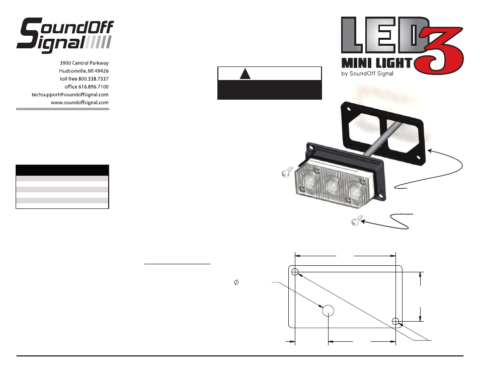
2x Supplied
#6 x 3/4” Sheet metal Screws
Supplied Gasket
EL3SN30(x) 4.10
WARNING
: Warning devices are strictly
regulated and governed by Federal, State and
Municipal ordinances. These devices shall be
used ONLY on approved vehicles. It is the sole
responsibility of the user of these devices to
ensure compliance.
SINGLE EXTERIOR
LED3 WARNING LIGHT
ASSEMBLY INSTRUCTIONS
EL3SN30(x)
!
WARNING
This product contains high intensity LED
devices. To prevent eye damage, DO NOT
stare into light beam at close range.
MOUNTING
Important: DO NOT over tighten
mounting screws or nuts. This could
cause permanent damage to the light.
1. Locate flat mounting location for the
LED3 Light.
2. When the position of LED3 is
determined use paper template on
next page to drill hole locations. Screw
mounting holes should be drilled using
a 3/32” drill bit. Wire entry holes
should be drilled using a 1/4” drill bit.
3. Make electrical connections.
4. Using supplied #6 x 3/4” screws, fasten
LED3 to mounting surface. Be sure
not to overtighten screws as this will
cause hole in mounting surface to strip
out. Be sure that supplied gasket is
mounted between mounting surface
and LED3.
NOTE: The LED3 is a factory sealed unit that
CANNOT be serviced in the field. Any
attempt to gain access to the LED3 unit
will most likely cause permanent damage
and void its warranty.
IMPORTANT: DO NOT connect this
device to a strobe power supply.
OPERATING INSTRUCTIONS
See Configuration Instructions.
The single LED3 comes equipped with an
internal flasher with 33 user selectable
patterns that can be synchronized either
alternating or simultaneous with up to
three other lights. It can also be put into
slave mode and driven through an
external flasher.
1. Connect the LED3 BLACK wire to a good,
convenient ground.
2. Connect the LED3 RED wire to one side
of a user supplied on/off switch. Connect
the other side of the switch, through a
5Amp fuse, to a source of +10-30Vdc.
2.5"W x 1.375"H x 1.25"D
33
10-30Vdc
0.5 Amps*
Yes
-40º to +65º C
*Pattern Dependent
TECHNICAL SPECIFICATIONS
Overall Dimensions:
Flash Patterns:
Input Voltage:
Current Consumption:
Light Sync Technology:
Operating Temperature:
2.21
1.085
1/4” DRILL
1.48
0.73
2xØ3/32”
Drill Template for Mounting Holes/Cord Entry
Template Shown Actual Size