Aileron servo and linkage installation rc option – E-flite PT-19 450 ARF User Manual
Page 6
6
E-flite PT-19 ARF Assembly Manual
8. Use a #1 Phillips screwdriver and a 2mm x 4mm
machine screw to secure the aileron pushrod wire.
Remove the low-tack tape from the aileron at this
time as well.
9. Repeat steps 1 through 8 to install the remaining
cover and aileron linkage.
Aileron Servo and Linkage Installation
RC Option
Required Parts
Radio system
Wing panel (left and right)
Servo (2)
Connector backplate (2)
Brass pushrod connector (2)
2mm x 4mm machine screw (2)
2mm x 8mm sheet metal screw (8)
6-inch (152mm) servo extension (2)
Aileron pushrod wire, 2
1
/
2
-inch (65mm) (2)
Required Tools and Adhesives
Pin drill
Drill bit: 1/16-inch (1.5mm)
Pencil
Phillips screwdriver: #0, #1
6-minute epoxy
Medium grit sandpaper
Mixing cup
Mixing stick
Thin CA
String/dental floss
Pliers
Low-tack tape
This section details the installation of the aileron
linkage for the radio controlled version of the
PT-19. If you are building the control line version
and have already installed the aileron linkage,
please skip this section of the manual.
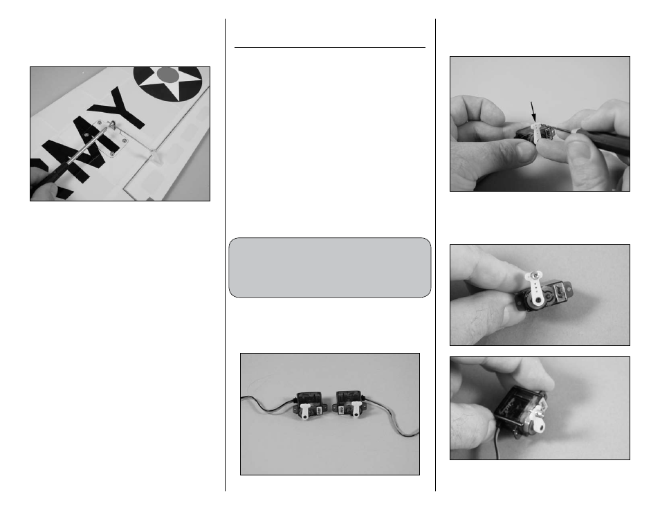
1. Use the radio system to center the aileron servos.
Use a #0 Phillips screwdriver to remove the control
horns and install them on the servos as shown.
Prepare a left and right aileron servo at this time.
2. Use a pin drill and 1/16-inch (1.5mm) drill bit
to enlarge the center outer hole of the servo arm
as shown.
3. Insert the brass pushrod connector into the hole.
Use pliers and the connector backplate to secure
the brass pushrod connector to the servo arm.