Joining the wing panels, rc and cl options – E-flite PT-19 450 ARF User Manual
Page 10
10
E-flite PT-19 ARF Assembly Manual
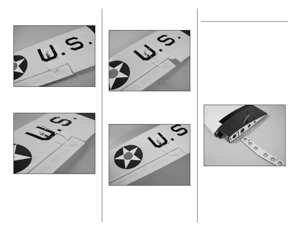
20. Use a #1 Phillips screwdriver to install the four
2mm x 8mm sheet metal screws that secure the
aileron servo cover to the wing.
21. Insert the Z-bend end of the 2
1
/
2
-inch (65mm)
aileron linkage in the outside hole of the aileron
control horn.
22 Insert the aileron pushrod in the hole of the
brass connector pushrod. Once the pushrod is
inserted into the connector, center the aileron using
low tack tape.
23. Make sure the aileron servo is centered from
Step 1. Use a #1 Phillips screwdriver and 2mm x
4mm machine screw to secure the aileron pushrod
in the brass pushrod connector. Once connected,
remove the low tack tape from the aileron.
24. Repeat steps 12 through 23 to mount the
remaining aileron servo to the servo cover and
install the aileron linkage.
Joining the Wing Panels,
RC and CL Options
Required Parts
Wing panel (right and left)
Wing joiner
4-40 x 1-inch socket head screw (2) (optional)
Required Tools and Adhesives
30-minute epoxy
Paper towel
Mixing cup
Mixing sticks
Epoxy brush
Rubbing alcohol
T-pin
Low-tack tape
Square
Pencil
Sandpaper: medium grit
Rubber bands (optional)
1. Use a pencil to mark the wing panel and wing
joiner. This is necessary as you will need to be able
to return the joiner back to the panels in which it
was fitted.