Elevator bellcrank installation cl option – E-flite PT-19 450 ARF User Manual
Page 20
20
E-flite PT-19 ARF Assembly Manual
Elevator Bellcrank Installation
CL Option
Required Parts
Wing assembly
Fuselage assembly
#4 washer (4)
Brass pushrod connector
4-40 x 1/2-inch socket head screw (4)
Connector backplate
2mm x 4mm machine screw
Elevator bellcrank assembly
Required Tools and Adhesives
Hobby knife with #11 blade
Pliers
Nut driver: 5.5mm
Ruler
Phillips screwdriver: #1
Felt-tipped pen
Trim seal iron
This section details the installation of the elevator
bellcrank for the control line version of the PT-19.
If you are building the radio controlled version,
please skip to the next section. If you plan on
using your model for both RC and CL, then you
will want to perform the steps in this section.
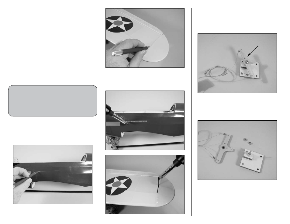
1. Use a hobby knife with a new #11 blade to cut
a slit in the covering on the left side of the fuselage
for the elevator leadout wires to exit. Also cut a slit
in the left wing tip for the leadout wire guide to fit
into the wing.
2. Use a trim seal iron to iron the covering at the
fuselage and wing tip to create a finished look to
your model.
3. Use a felt-tipped pen to mark the top of the
elevator bellcrank as shown. This is necessary
as the bellcrank must be disassembled to fit into
the fuselage and returned to its proper position
when reassembled.
4. Use a 5.5mm nut driver to remove the nut from
the bellcrank assembly. Remove the flanged washer
and bellcrank from the bellcrank assembly base.
Place all items aside for later.