E-flite PT-19 450 ARF User Manual
Page 36
36
E-flite PT-19 ARF Assembly Manual
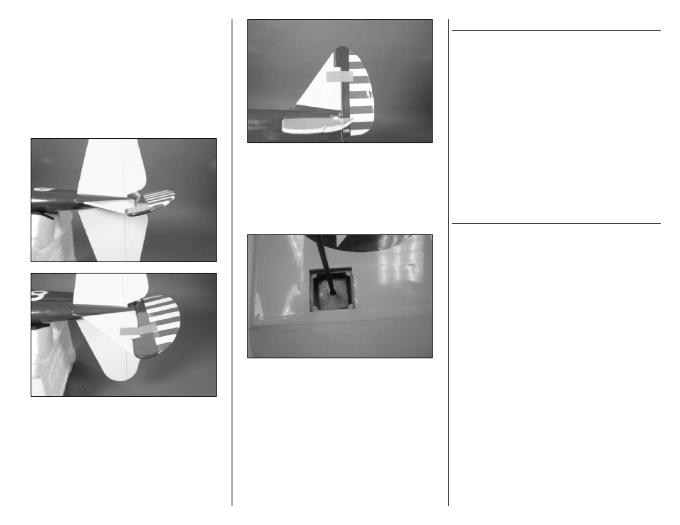
You will need to set the rudder offset next. This is
done by placing a piece of tape on each side of the
rudder/vertical fin joint as shown in the photo below.
Be sure to tape the rudder with an offset to the right
to help pull the model outboard of the circle being
flown. The model will fly in a counterclockwise rotation
and needs right rudder for the offset. The amount of
offset is not extremely critical for the PT-19. Measuring
at approximately 3/8–1/2 inch of right offset will
deliver a nice strong pull during flight without any bad
tendencies during basic maneuvering.
Be sure to place 3/4-ounce of tip weight in the tip
weight box located under the right wing tip. This will
help hold the model level and counter the balance
effects of the lines. We use Sig 1/4-ounce tip weights
(SIGSH561). These weights are available at your local
hobby shop. You may vary the amount of weight at
your discretion to fine-tune the flight qualities of your
PT-19.
Finally, you will need to do the installation of the
bellcrank and leadouts as described in the manual on
pages 18 and 29. Once this has been accomplished
you need only remove the four 4-40 bolts and insert the
servo tray back in place after flying. Please follow the
steps in the section titled “Leadout Guide Installation and
Tip Weight Box CL Option” beginning on page 29 of
the manual.
MOTOR SELECTION
There are two motor selections for your PT-19: the Park
450 and Park 480 outrunner motors. The PT-19 will fly
on either motor when being flown using the control line
option. Please note the following:
Park 450: When flying your PT-19 using the Power
450 motor, ensure the winds are light (less than 5mph)
and limit your aerobatic maneuvers to basic loops,
climbing and diving.
Park 480: When flying your PT-19 using the Park 480
motor, ensure winds are light (less than 5mph) and you
can perform the basic aerobatic maneuvers without
any problems: loops, inverted flight, wing overs, lazy
eights, square loops, etc. The PT-19 was not designed
to fly the entire AMA pattern of maneuvers, but can
provide many hours of enjoyable control line flying.
CONTROL LINE FLYING AT THE FIELD
Once you have the model set up and are ready to fly,
we will want to double check a few items before taking
to the air. Follow this simple checklist before your first
flight to ensure everything is correct.
1. Ailerons locked in position
2. Rudder locked in position
3. Tip weight installed
4. Control line connectors secure
5. Handle connectors secure
Now we will need to ensure our flying area is clear
of any obstructions. The lines used are 52 feet long.
You will need a clear circle of 125 feet in diameter
for flying the PT-19. Keep in mind that onlookers
may come to watch and ensure you have a helper
to keep the circle clear during flight. The PT-19 has
been designed to deliver nice smooth control line
flight with some very basic aerobatic abilities. The
model is capable of wing-overs, loops (both inside
and outside), inverted flight, and lazy eights. Other
maneuvers may be possible but understand the PT-19
is not designed as a serious stunt machine. You will
find the takeoffs to be easy and quick as well as the
basic flight performance. Landings are easily guided
down as well. Please note the diagrams showing wing
direction and placement for takeoff and maneuvering
as the wind plays a major part in line tension during
these maneuvers.