E-flite PT-19 450 ARF User Manual
Page 17
17
E-flite PT-19 ARF Assembly Manual
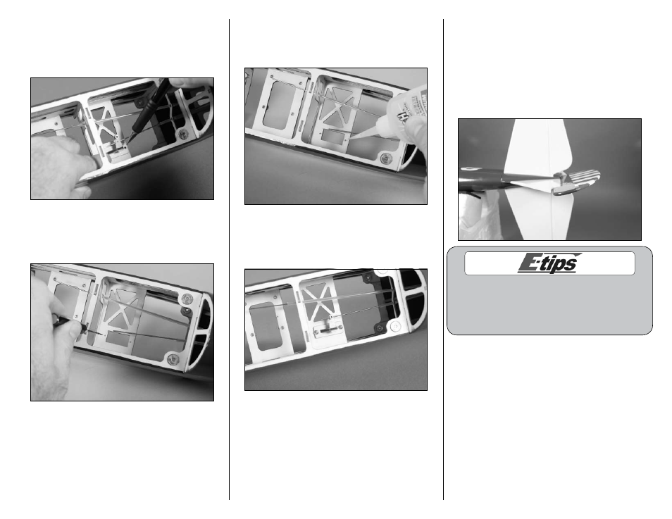
3. Center the rudder linkage stay over the opening
in the servo tray inside the fuselage with the
pushrod connector toward the tail of the fuselage.
Use a pencil to mark the positions for the servo
mounting screws onto the servo tray.
4. Remove the rudder servo. Use a pin drill
and 1/16-inch (1.5mm) drill bit to drill a hole
in the servo tray at the position marked in the
previous step.
5. Place 2–3 drops of thin CA into each of the
holes to harden the surrounding wood. This will
provide a harder surface for the screws to bite into
and make them more secure when installed.
6. Mount the rudder linkage stay to the servo tray
using two 2mm x 8mm sheet metal screws. Use a
#1 Phillips screwdriver to tighten the screws. Slide
the pushrod into the pushrod connector at this time.
7. Position the rudder so there is a small amount
of offset to the rudder as shown. This is necessary
as the model will fly in a counterclockwise rotation
and needs right rudder for the offset. The amount
of offset is not extremely critical for the PT-19.
Measuring at approximately 3/8–1/2 inch of
right offset will deliver a nice strong pull during
flight without any bad tendencies during basic
maneuvering.
We recommend 1/2 inch rudder offset for your
first flights if you have not flown CL before or it
has been a long time since that last flight. You can
reduce this over time to meet the personalized
feel and performance of your PT-19.