Stabilizer and fin installation rc/cl options – E-flite PT-19 450 ARF User Manual
Page 14
14
E-flite PT-19 ARF Assembly Manual
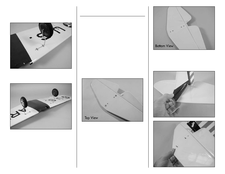
2. Use two landing gear straps and four 2mm
x 8mm sheet metal screws to secure the landing
gear to the bottom of the wing. Use a #1 Phillips
screwdriver to tighten the four screws.
3. Repeat Steps 1 and 2 to install the remaining
main landing gear to the bottom of the wing.
Stabilizer and Fin Installation
RC/CL Options
Required Parts
Stabilizer assembly Vertical fin assembly
#4 washer (4)
4-40 locknut (2)
Fuselage
4-40 x 1/2-inch socket head screw (2)
Rudder pushrod wire, 18
3
/
8
-inch (467mm)
Elevator pushrod wire, 20
1
/
2
-inch (521mm)
Required Tools and Adhesives
Threadlock
Nut driver: 1/4-inch
Ball driver or hex wrench: 3/32-inch
1. Locate the horizontal stabilizer and determine
the top and bottom as shown in the photos below.
The top will have the blind nuts, and the control
horn will face to the bottom.
2. Locate the vertical fin assembly. Slide the
threaded rods from the fin through the holes in the
stabilizer. The blind nuts in the stabilizer will fit into
the recesses in the vertical fin fairing.