Rudder servo installation cl option – E-flite PT-19 450 ARF User Manual
Page 16
16
E-flite PT-19 ARF Assembly Manual
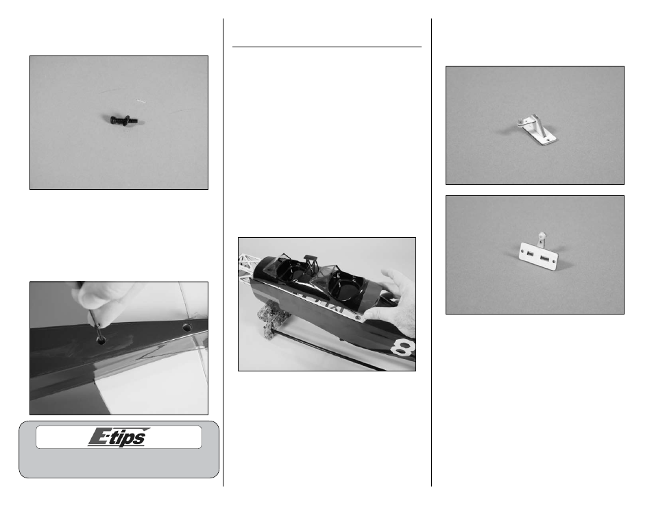
9. Slide a #4 washer on a 4-40 x 1/2-inch socket
head screw. Prepare two of these to secure the tail
to the fuselage.
10. Insert a 4-40 screw and washer into each of
the holes at the rear of the fuselage. Use a 3/32-
inch ball driver or hex wrench to tighten the two
screws. Do not over-tighten the screws and damage
the structure of the stabilizer or fuselage. They only
need to be tight enough to prevent the assembly
from moving when it is installed.
Always use threadlock on metal-to-metal fasteners
to prevent them from vibrating loose.
Rudder Servo Installation
CL Option
Required Parts
Fuselage assembly
Rudder linkage stay
Connector backplate
Brass pushrod connector
2mm x 4mm machine screw
2mm x 8mm sheet metal screw (2)
Required Tools and Adhesives
Pin drill
Drill bit: 1/16-inch (1.5mm)
Pencil
Thin CA
Pliers
Phillips screwdriver: #1
Ruler
1. Remove the cockpit hatch by lifting it upward at
the rear and sliding it back slightly to release the
pegs at the front. Set the cockpit hatch aside.
2. Insert the brass pushrod connector into the outer
hole of the rudder linkage stay. Use pliers and the
connector backplate to secure the brass pushrod
connector.